


148 CHAPTER 4: FLEXIBLE INTERFACE CARDS
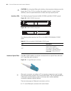
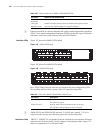
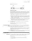
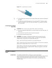
Interface LEDs The following figure illustrates an FIC-1FE panel.
Figure 168 FIC-1FE panel
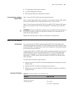
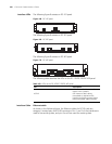
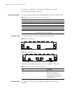
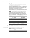
The following figure illustrates an FIC-2FE panel.
Figure 169 FIC-2FE panel
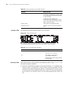
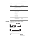
The following figure illustrates an FIC-4FE panel.
Figure 170 FIC-4FE panel
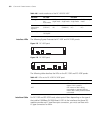
The following table describes the LEDs on the FIC-1FE/FIC-2FE/FIC-4FE panel.
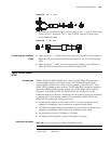
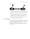
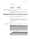
Interface Cable Ethernet cable
As shown in the following figure, the Ethernet cables for FIC-FE cards are
category-5 twisted pairs with RJ-45 connectors. Pins 1 and 2 of the interface are
used for transmitting data, and pins 3 and 6 are used for receiving data.
Table 103 LEDs on the FIC-1FE/FIC-2FE/FIC-4FE panel
LED Description
LINK OFF means no link is present; ON
means a link is present.
ACTIVE OFF means no data is being
transmitted or received on the
interface and blinking means data is
being transmitted and/or received.