


210 CHAPTER 4: FLEXIBLE INTERFACE CARDS
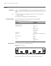
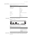
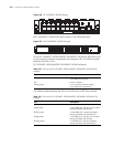
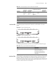
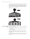
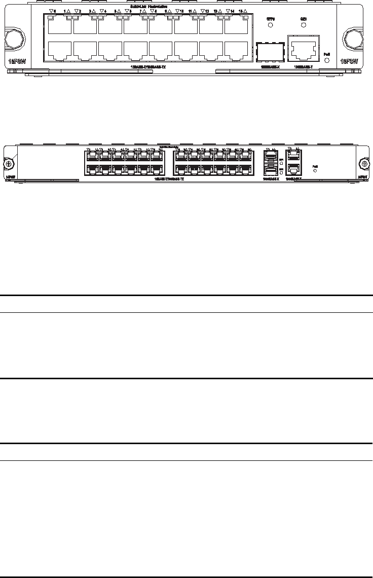
Figure 256 FIC-16FSW/FIC-16FSW-PoE panel
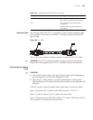
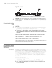
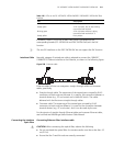
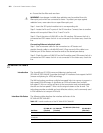
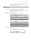
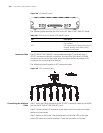
DFIC-24FSW/DFIC-24FSW-PoE panel is shown in the following figure:
Figure 257 DFIC-24FSW/DFIC-24FSW-PoE panel
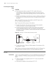
On the FIC-16FSW/FIC-16FSW-PoE/DFIC-24FSW/DFIC-24FSW-PoE panel each port
on the network connector corresponds with one green LED. The following table
describes the LEDs on the
FIC-16FSW/FIC-16FSW-PoE/DFIC-24FSW/DFIC-24FSW-PoE panel.
The following table describes the LEDs on the GE port and SFP fiber interface:
Table 154 LEDs on the FIC-16FSW/FIC-16FSW-PoE/DFIC-24FSW/DFIC-24FSW-PoE FE
interface
LED Description
Steady green A link is present, but no data is being
transmitted and received.
OFF No link is present.
Blinking green A link is present and data is being
transmitted and received (ACT).
Table 155 LEDs on the FIC-16FSW/FIC-16FSW-PoE/DFIC-24FSW/DFIC-24FSW-PoE GE
interface
LED Description
OFF No link is present.
Steady green A 1000 Mbps link is present, but no data is
being transmitted and received.
Blinking green A 1000 Mbps link is present and data is
being transmitted and received (ACT).
Steady yellow A 100 Mbps link is present, but no data is
being transmitted and received.
Blinking yellow A 100 Mbps link is present and data is
being transmitted and received (ACT).