


156 CHAPTER 4: FLEXIBLE INTERFACE CARDS
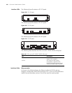
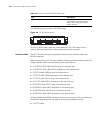
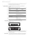
The following figure shows the FIC-8SAE panel:
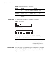
Figure 180 FIC-8SAE front panel
On the FIC-8SAE panel, each link corresponds to a LED. ON means a link is
present; blinking means data is being transmitted and/or received.
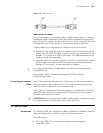
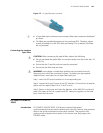
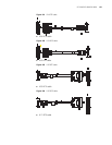
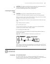
Interface Cable The FIC-SAE cards use synchronous/asynchronous serial interface cables with
DB-28 connectors.
Before connecting an FIC-SAE card, identify the line properties and then select the
proper interface cable from the following ten cable options:
■ V.24 (RS232) DTE cable: DB-25 plug at the network end
■ V.24 (RS232) DCE cable: DB-25 receptacle at the network end
■ V.35 DTE cable: 34PIN plug at the network end
■ V.35 DCE cable: 34PIN receptacle at the network end
■ X.21 DTE cable: DB-15 plug at the network end
■ X.21 DCE cable: DB-15 receptacle at the network end
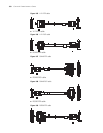
■ RS449 DTE cable: DB-37 plug at the network end
■ RS449 DCE cable: DB37 receptacle at the network end
■ RS530 DTE cable: DB-25 plug at the network end
■ RS530 DCE cable: DB25 receptacle at the network end
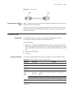
All these cables use a DB-28 connector to connect the router, but the connector at
the network end varies with the type of the to-be-connected network.
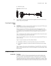
■ V.24 DTE cable
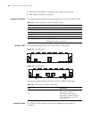
ACT OFF means no data is being
transmitted or received. Blinking
means data is being transmitted
and/or received.
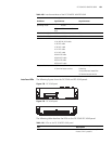
Table 110 LEDs on the FIC-2SAE/FIC-4SAE panel
LED Description