


FIC-1T1/FIC-2T1/FIC-4T1 and FIC-1T1-F/FIC-2T1-F/FIC-4T1-F 175
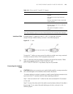
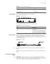
Interface Cable Interface cables (T1 cables) for the FIC-T1/FIC-T1-F cards are 100-ohm
straight-through shielded cables, as shown in the following figure:
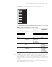
Figure 217 T1 cable
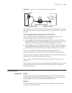
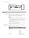
To extend a T1 cable, you may connect the cable to another one using a network
interface connector with an RJ-45 receptacle at each end.
n
Both T1 cable and network interface connector are optional accessories. Please
order them together with FIC-1T1/FIC-2T1/FIC-4T1 and
FIC-1T1-F/FIC-2T1-F/FIC-4T1-F. By default, they are not provided.
Connecting the Interface
Cable
c
CAUTION: Before you connect a port, read its label carefully; a wrong connection
can cause damages to the interface card and even the device.
If outdoor cabling is involved, consider to install a special lightning arrester at the
input end of the T1 interface cable for better lightning protection.
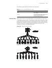
Step 1: Insert one end of the T1 cable into the to-be-connected RJ-45 connector
on the card.
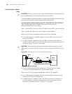
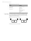
Step 2: Connect the other end of the cable to another device directly if the cable is
long enough. If not, extend the cable before you do that, as shown in the
following figure:
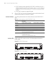
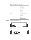
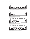
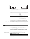
Table 119 LEDs on the FIC-T1 and FIC-T1-F panels
LED Description
LINK/ACT ON means the carrier signal has been
received.
OFF means no carrier signal has been
received.
Blinking means data is being transmitted
or/and received.
LP/AL ON means the interface is in a loopback.
Blinking means an AIS, LFA, or RAI alarm
signal is present.
OFF means no loopback or alarm is
present.
Note:
AIS = Alarm indication signal; LFA = loss of frame alignment; RAI = Remote alarm indication