


FIC-1CE3 179
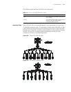
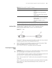
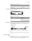
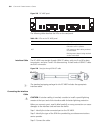
Interface LEDs The following figure illustrates an FIC-1CE3 panel.
Figure 221 FIC-1CE3 panel
The following table describes the LEDs on the card panel.
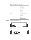
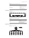
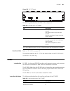
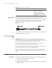
Interface Cable The external interface provided by the FIC-1CE3 uses two SMB sockets respectively
for data transmitting (Tx) and data receiving (Rx). The interface transmits in
75-ohm unbalanced mode and uses a pair of 75-ohm unbalanced coaxial cables to
connect another device.
Figure 222 E3/T3 cable
n
The FIC-1CE3 and the FIC-1CT3 use the same cable, called E3/T3 cable in this
manual.
The standard equipping package of the FIC-1CE3 does not include the interface
cable.
Connecting the Interface
Cable
c
CAUTION: By design, the FIC-1CE3 is protected against lightning strikes. But
when outdoor cabling is involved, you are recommended to add a special lightning
arrester at the input end of the E3/T3 cable for better protection.
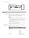
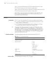
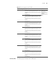
Operating mode E3
CE3
Supported service E3 leased line
Table 122 FIC-1CE3 interface attributes
Attribute Description
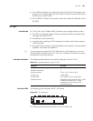
Table 123 LEDs on the FIC-1CE3 panel
LED Description
LINK OFF means no link is present; ON means a
link is present.
ACT OFF means no data is being transmitted or
received on the interface; blinking means
data is being transmitted and/or received.
BNC connector SMB connectorBNC connector SMB connectorBNC connector SMB connectorBNC connector SMB connectorBNC connector SMB connector