


208 CHAPTER 4: FLEXIBLE INTERFACE CARDS
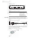
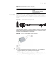
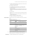
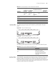
Figure 255 T1 cable
You can also use a network interface connector to extend the FIC-1VTI cable.
c
CAUTION: The corresponding cables are not included in the standard shipment
package of FIC-1VT1. Please order them together with FIC-1VT1. By default, they
are not supplied.
Connecting the Interface
Cable
c
CAUTION:
■ You should connect a cable to the port with the correct mark. Misplugging is
prone to impair the card and even damage the router.
■ When using T1 cable outdoors, you are recommended to install a special
lightning arrester on the input end of the cable in order to avoid lightning more
effectively.
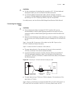
If the FIC has been properly installed, follow these steps to connect the cable:
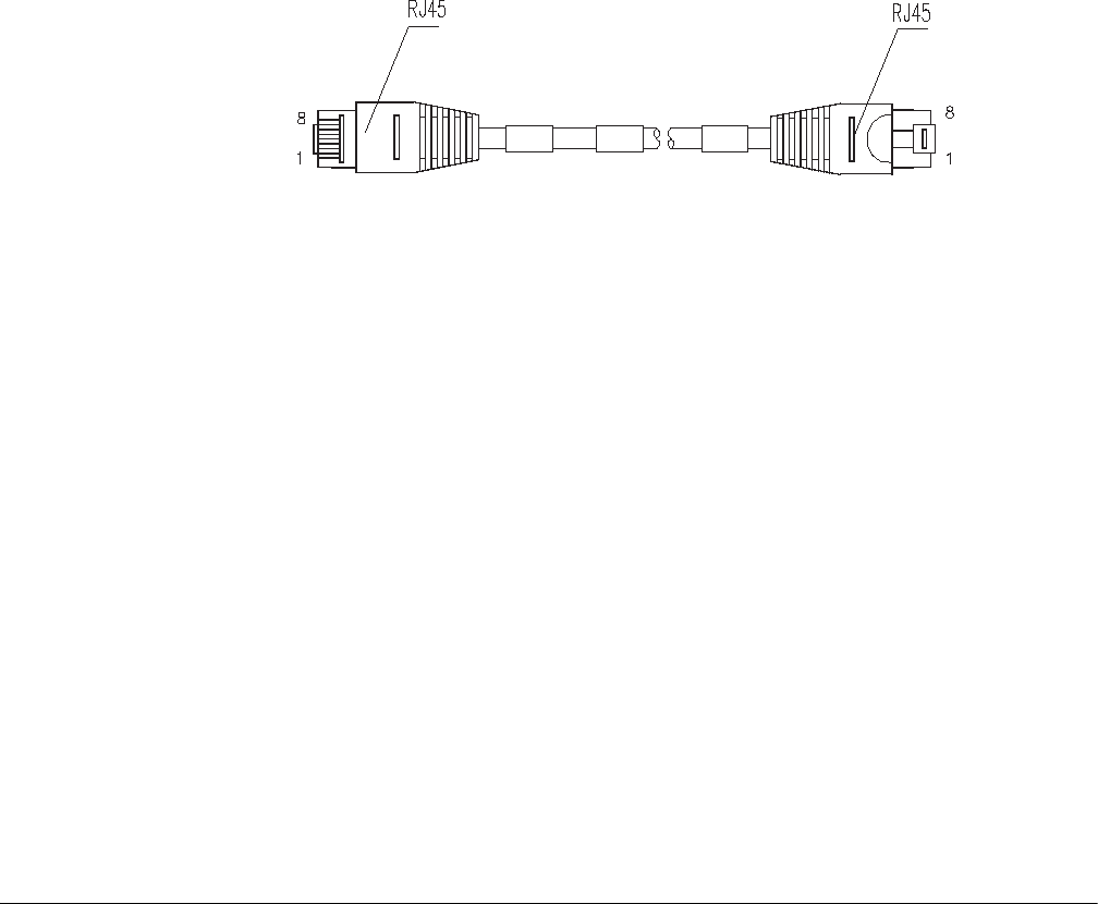
Step 1: Plug one end of T1 cable into the RJ45 connector of FIC-1VT1.
Step 2: Connect the other end of T1 cable to the peer device;
Step 3: Check the status of LINK LED on the FIC-1VT1 panel: OFF means the link is
not connected. In the latter case, check the line.
FIC-16FSW/FIC-16FSW-
PoE/DFIC-24FSW/DFIC-
24FSW-PoE
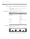
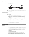
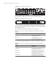
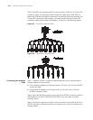
Introduction The 16/24-port 10/100 Mbps Ethernet Layer 2 switching MIM interface module
(FIC-16FSW/FIC-16FSW-PoE/DFIC-24FSW/DFIC-24FSW-PoE) is used on H3C MSR
50 series router. A router installed with FIC-16FSW/DFIC-24FSW modules can work
as a switching/routing integrated device on a small-sized enterprise network to
connect PCs and network devices inside the network directly. The interfaces
provided on the FIC-16FSW/FIC-16FSW-PoE and DFIC-24FSW/DFIC-24FSW-PoE
are as follows:
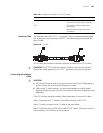
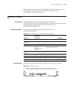
FIC-16FSW/FIC-16FSW-PoE provides:
■ 16 10/100 Mbps RJ45 connector interfaces on the FIC-16FSW module
■ One 10/100/1000 Mbps gigabit RJ45 connector electrical interfaces on the
FIC-16FSW module