


60 CHAPTER 2: SMART INTERFACE CARDS
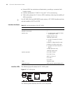
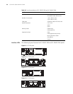
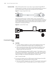
Interface Cable When a BSV interface works in user mode, it uses a straight-through ISDN S/T
interface cable for connection, with pins 3 and 6 for data transmission and pins 4
and 5 for data receiving. At both ends of the cable are RJ-45 connectors.
Figure 57 Straight-through ISDN S/T cable
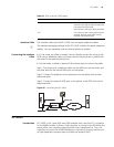
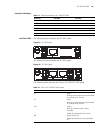
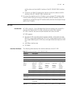
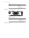
When a BSV interface works in network mode, it uses a crossover ISDN S/T
interface cable for connection, with pins 3 and 6 for data transmission and pins 4
and 5 for data receiving. At one end of the cable is an RJ-45 plug for connecting
the SIC-1BSV/SIC-2BSV interface and at the other end of the cable is an RJ-45
receptacle for connecting a TE device.
Figure 58 Crossover ISDN S/T cable
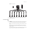
Connecting the Interface
Cable
c
CAUTION:
■ If outdoor cabling is involved, you need to install a lightning arrester at the
input end of the ISDN BRI S/T interface cable to avoid lightning strike.
■ When connecting the interface cable to the interface, pay attention to the
mark on the interface to avoid wrong insertion, which may damage the
interface card or even the router host.
Step 1: Decide the operating mode of the BSV interface. If the interface is to be
connected to an ISDN network, it should operate in user mode; if the interface is
to be connected to a TE device (a digital phone or another BSV interface in user
mode for example), the interface should operate in network mode.
Step 2: Connect the cable.
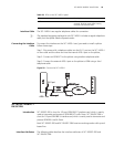
1 To connect the interface card to an ISDN network, identify the type of the ISDN
line provided by your telecommunications service provider.
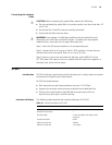
■ If the line is an ISDN U-interface line, use an NT1 for conversion. Insert one end
of the straight-through S/T interface cable into the S/T interface of the NT1,
Green
Yellow
Red
Black
Yellow
Green
Black
Red
Green
Yellow
Red
Black
Yellow
Green
Black
Red
Green
Yellow
Red
Black
Yellow
Green
Black
Red
Green
Yellow
Red
Black
Yellow
Green
Black
Red