


218 CHAPTER 4: FLEXIBLE INTERFACE CARDS
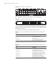
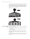
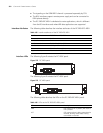
The following table describes the LEDs on the FIC-1SHL-4W panel.
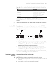
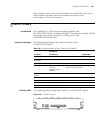
Interface Cable The FIC-1SHL-4W uses a tailor-made 4-wire telephone cable of type “Y” or “I”.
You can select the type as needed.
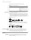
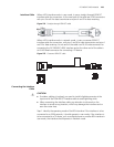
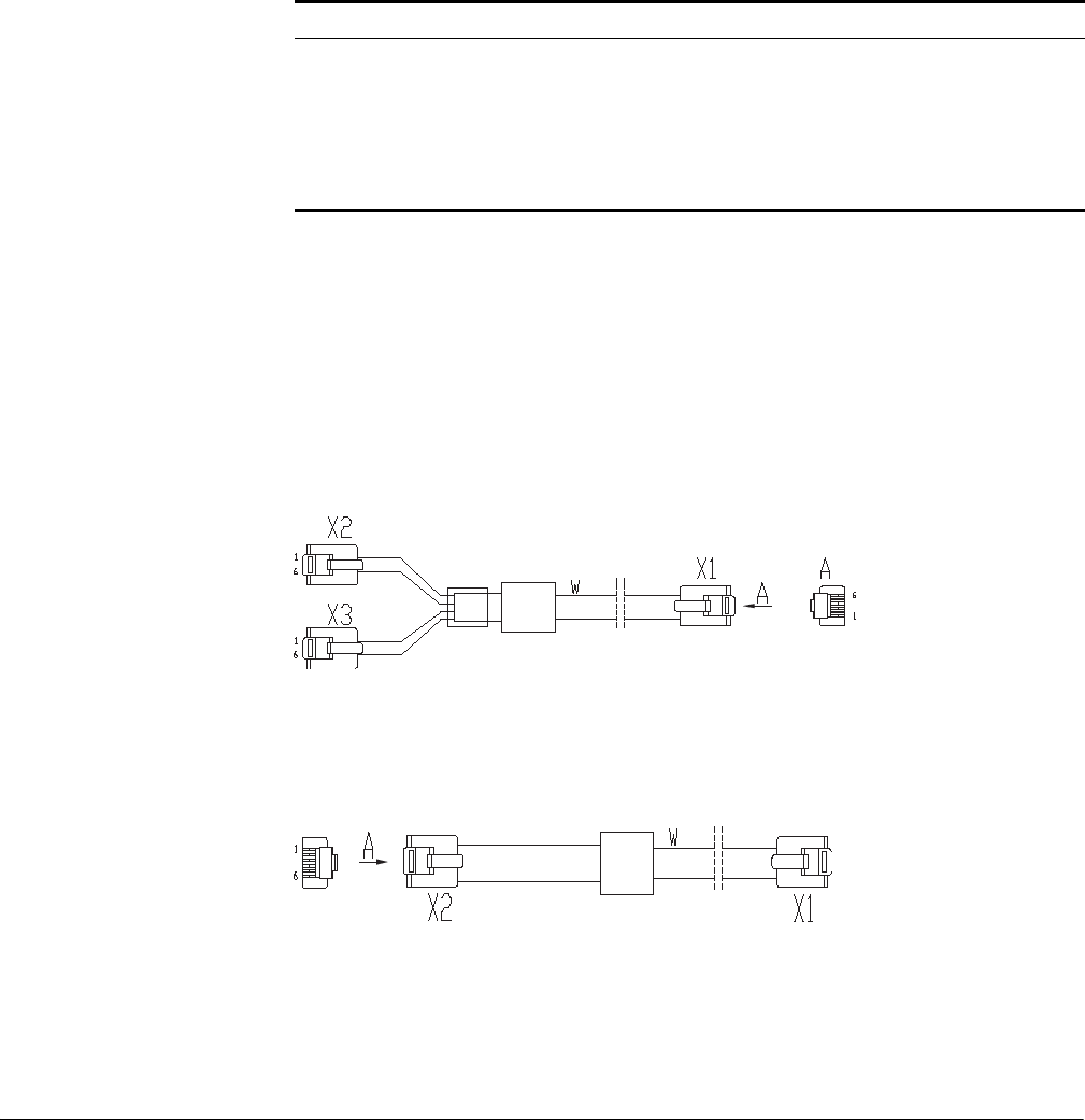
■ As shown in the following figure, on one end of the type “Y” G.SHDSL cable
there is one RJ-11 connector (X1), which is used to connect the FIC-1SHL-4W
card. On the other end there are two RJ-11 connectors (X2 and X3), which can
connect two 2-wire telephone cables. On X1, pins 3 and 4 are connected with
pins 3 and 4 on X2, and pins 2 and 5 are connected with pins 3 and 4 on X3.
Figure 267 Type “Y” cable
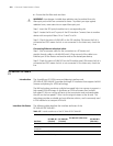
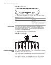
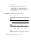
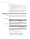
■ As shown in the following figure, on the two ends of the “I” type G.SHDSL
cable there are RJ-11 connectors, which can connect one 4-wire telephone
cables.
Figure 268 “I” type cable
Connecting the Interface
Cable
■ When using “Y” cable, connect the X1 end of the cable to the interface on
FIC-1SHL-4W and connect the other two ends to DSLAM through PSTN.
■ When using “I” cable, connect one end of the cable to the interface on
FIC-1SHL-4W and the other end to DSLAM through PSTN.
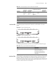
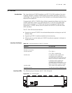
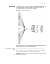
FIC-1CPOS
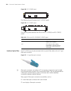
Introduction The 1-port channelized SDH/SONET interface card (FIC-1CPOS) provides one
STM-1/OC3-compliant multi-channel interface and supports communication
speeds up to 155.52 Mbps.
Table 162 LEDs on the FIC-1SHL-4W panel
LED Description
LINK OFF means no link is present.
ON means a link is present.
ACT OFF means no data is being transmitted or
received.
Blinking means data is being received or
transmitted.