


164 CHAPTER 4: FLEXIBLE INTERFACE CARDS
Interface Cable Interface cable of the FIC-1E1/FIC-2E1 and the FIC-1E1-F/FIC-2E1-F
Interface cables for the FIC-1E1/FIC-2E1 and FIC-1E1-F/FIC-2E1-F are
G.703-compliant cables, also known as E1 cables. The cables are divided into two
categories: 75-ohm unbalanced coaxial and 120-ohm balanced twisted-pair.
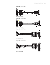
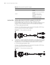
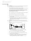
■ 75-ohm unbalanced coaxial cable
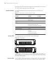
As shown in the following figure, at the router end of the cable is a DB-15 plug
and at the network end are two BNC receptacles.
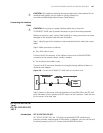
Figure 200 E1 75-ohm unbalanced coaxial cable
n
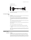
To extend an E1 75-ohm unbalanced coaxial cable, you can select a pair of coaxial
connectors with a BNC receptacle at each end to connect the BNC receptacles of
the cable each to a 75-ohm unbalanced coaxial cable with BNC connectors.
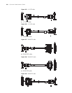
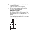
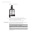
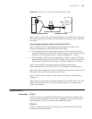
■ 120-ohm balanced twisted-pair cable
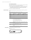
As shown in the following figure, at the router end of the cable is a DB-15 plug
and at the network end is an RJ-45 connector.
Figure 201 E1 120-ohm balanced twisted-pair cable
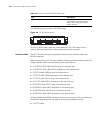
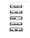
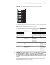
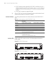
Table 113 LEDs on the FIC-E1 and FIC-E1-F panels
LED Description
LINK ON means the carrier signal has been
received.
OFF means no carrier signal has been
received.
ACTIVE OFF means no data is being
transmitted or received on the
interface.
Blinking means data is being
transmitted and/or received.