


24 CHAPTER 2: SMART INTERFACE CARDS
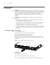
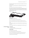
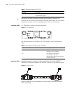
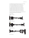
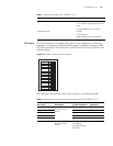
Interface LEDs SIC-1SAE panel is shown in the following figure:
Figure 7 SIC-1SAE panel
Description of the LEDs on SIC-1SAE panel is given in the following table:
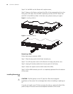
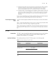
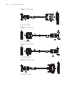
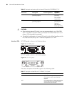
Interface Cable The SIC-1SAE uses a synchronous/asynchronous serial interface cable with DB-28
connectors for connection.
Before connecting to a port on the SIC-1SAE, confirm the line properties of the
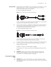
interface to select an appropriate cable from the following cable options:
■ V.24 (RS232) DTE cable: DB-25 (male) connector at the network end
Cable V.24 (RS232) DTE cable
V.24 (RS232) DCE cable
V.35 DTE cable
V.35 DCE cable
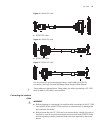
X.21 DTE cable
X.21 DCE cable
RS449 DTE cable
RS449 DCE cable
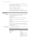
RS530 DTE cable
RS530 DCE cable
Supported service 1) DDN leased line
2) Terminal access service
1) Dialup through modems
2) Backup
3) Asynchronous leased line
4) Terminal access
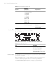
Table 3 Interface attributes of the SIC-1SAE
Attribute
Description
Synchronous Asynchronous
Table 4 LEDs on SIC-1SAE panel
LED Description
LINK OFF means no link is present;
ON means a link is present.
ACT OFF means no data is being
transmitted or received;
Blinking means data is being received
or/and transmitted.