


200 CHAPTER 4: FLEXIBLE INTERFACE CARDS
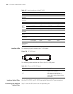
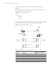
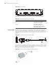
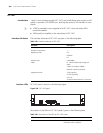
Figure 244 FIC-2VE1 panel
Description of the LEDs on FIC-2VE1 panel is given in the following table:
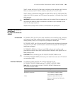
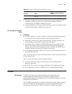
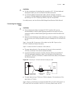
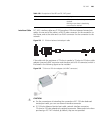
Interface Cable FIC-2VE1 interface cables are G.703-compliant 120-ohm balanced twisted pair
cables. At one end of the cable is a DB-15 male connector for the connection to
the Router, and at the other end is an RJ-45 connector for the connection to the
network.
Figure 245 E1 120-ohm balanced twisted pair cable
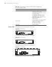
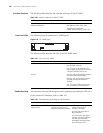
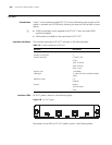
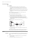
If the cable with the resistance of 75-ohm is needed, a 75-ohm-to-120-ohm cable
adapter (one end is BNC connector and the other end is RJ-45 connector) which is
illustrated in the following figure can be installed.
Figure 246 75-ohm-to-120-ohm adapter (with BNC connector)
Table 146 Description of the LEDs on FIC-2VE1 panel
LED Description
LINK OFF means no link is present;
ON means a link is present.
ACTIVE OFF means no data is being
transmitted or received.
Blinking means there is data being
transmitted or received.