


FIC-4BSE 181
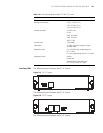
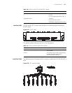
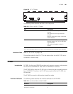
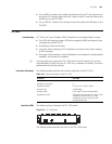
Figure 223 FIC-1CT3 panel
The following table describes the LEDs on the card panel.
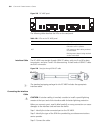
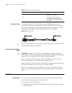
Interface Cable Refer to “FIC-1CE3” on page 178.
The interface cable for the FIC-1CT3 is the same as that for the FIC-1CE3 and is
connected in the same way.
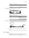
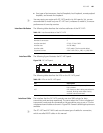
FIC-4BSE
Introduction FIC-4BSE, the four-port ISDN BRI interface card, transmits, receives, and processes
four channels of ISDN BRI S/T data traffic on ISDN BRI S/T interfaces.
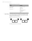
The FIC-4BSE differs from the FIC-4BS only in the way they set matched resistance
for an ISDN BRI S/T interface: the FIC-4BS uses jumpers while the FIC-4BSE uses
DIP switches.
The FIC-4BSE can work in dial mode or leased line mode.
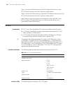
Interface Attributes The following table describes the interface attributes of the FIC-4BSE.
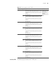
Table 125 LEDs on the FIC-1CT3 panel
LED Description
LINK/ACT ON means the carrier signal has been
received.
OFF means no carrier signal has been
received.
Blinking means data is being transmitted
or/and received.
LP/AL ON means the interface is in a loopback.
Blinking means an AIS, LFA, or RAI alarm
signal is present.
OFF means no loopback or alarm is
present.
Note:
AIS = Alarm indication signal; LFA = loss of frame alignment; RAI = Remote alarm indication
Table 126 Interface attributes of the FIC-4BSE
Attribute Description
Connector RJ-45
Number of connectors 4