


FIC-2VT1 203
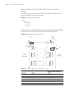
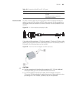
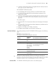
Interface Cable The interface cable of FIC-2VT1 is a standard 100-ohm standard shielding cable.
The connectors on the two ends use RJ 45. The following figure illustrates this
type of cable.
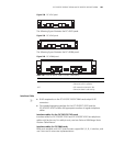
Figure 249 T1 cable
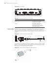
You can also use a network interface connector to extend the FIC-2VTI cable.
c
CAUTION: The FIC-2VTI cable and network interface connector are optional.
Please order them together with FIC-2VT1. By default, they are not supplied.
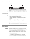
Connecting the Interface
Cable
c
CAUTION:
■ You should connect a cable to the port with the correct mark. Misplugging is
prone to impair the card and even damage the router.
■ When using T1 cable outdoors, you are recommended to install a special
lightning arrester on the input end of the cable in order to avoid lightning more
effectively.
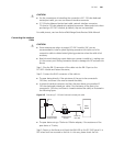
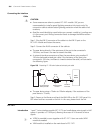
If the FIC has been properly installed, follow these steps to connect the cable:
Step 1: Plug one end of T1 cable into the RJ45 connector of FIC-2VT1.
Step 2: Connect the other end of T1 cable to the peer device;
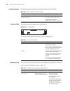
Step 3: Check the status of LINK LED on the FIC-2VT1 panel: OFF means the link is
not connected. In the latter case, check the line.
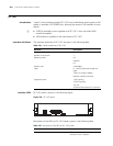
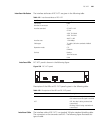
Table 148 Description of the LEDs on FIC-2VT1 panel
LED Description
LINK ON means carrier signal is received;
OFF means no carrier signal is received.
ACT OFF: No data is being received and
transmitted;
Blinking: Data is being received and
transmitted.