


30 CHAPTER 2: SMART INTERFACE CARDS
c
CAUTION:
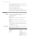
■ When setting internal DIP switch, you are recommended to: turn ON all BITs
from 1 to 8 when a 75-ohm cable is connected. Turn OFF all BITs from 1 to 8
when a 120-ohm cable is connected;
■ The default configuration of internal DIP switch is that all the 8 positions of the
BIT switch are ON, that is, the E1 interface impedance is 75-ohm.
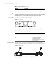
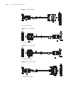
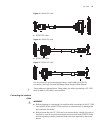
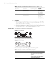
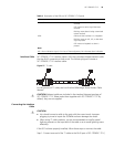
Interface LEDs SIC-1EPRI panel is shown in the following figure:
Figure 19 SIC-1EPRI panel
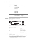
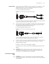
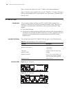
SIC-1E1-F panel is shown in the following figure:
Figure 20 SIC-1E1-F panel
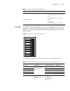
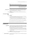
The status description of the LEDs is given in the following table:
7BIT Switch for RxShield
grounding options
- ON: RxShield
grounding
OFF: RxShield
ungrounding
8BIT Switch for RxShield
grounding options
- OFF: RxShield
grounding via
capacitor
ON: RxShield
directly grounding
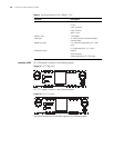
Table 6 Description and settings of the internal DIP switch of SIC-ERRI/SIC-1E1-F
DIP switch Description 75-ohm impedance
120-ohm
impedance
Table 7 Description of the LEDs on SIC-1EPRI/SIC-1E1-F panel
LED Description
LINK ON means carrier signal has been received.
OFF means no carrier signal has been
received.
ACT OFF means no data is being transmitted or
received; blinking means data is being
received or/and transmitted.
Fractional E1