


SIC-1BSV/SIC-2BSV 59
Interface Attributes
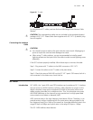
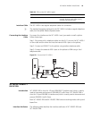
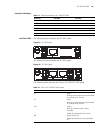
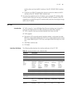
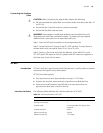
Interface LEDs The following figure illustrates the SIC-1BSV panel.
Figure 55 SIC-1BSV panel
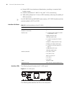
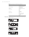
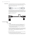
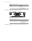
The following figure illustrates the SIC-2BSV panel.
Figure 56 SIC-2BSV panel
The following table describes the LEDs on SIC-1BSV/SIC-2BSV panel.
Table 31 Interface attributes of SIC-1BSV/SIC-2BSV
Attribute SIC-1BSV SIC-2BSV
Connector RJ45
Number of connectors 1 2
Interface standard ITU-T I.430, Q.921, Q.931
Interface rate 192 Kbps
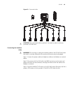
Cable ISDN S interface cable
Supported service Voice access over ISDN S interface cable
Table 32 LEDs on SIC-1BSV/SIC-2BSV panel
LED Description
B1 Green
Blinking indicates data is being transmitted
or received on B1 channel.
B2 Green
Blinking indicates data is being transmitted
or received on B2 channel.
ACT Yellow
Blinking indicates the link is being
activated.
Steady ON indicates the link is active.
ON Green, power LED.
Steady ON indicates the card is powered
on.