


86 CHAPTER 3: MULTIFUNCTIONAL INTERFACE MODULES
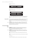
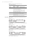
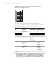
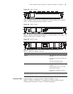
Figure 96 Default setting of DIP switches for MIM-1E1/MIM-2E1/MIM-4E1 and
MIM-1E1-F/MIM-2E1-F/MIM-4E1-F modules
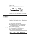
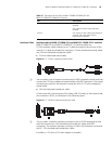
Description of DIP switch settings is given in the following table for
MIM-1E1/MIM-2E1/MIM-4E1 and MIM-1E1-F/MIM-2E1-F/MIM-4E1-F modules:
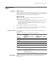
c
CAUTION:
■ It is recommended to select the DIP switch of MIM-1E1/MIM-2E1/MIM-4E1 and
MIM-1E1-F/MIM-2E1-F/MIM-4E1-F modules in this way: when connecting
75-ohm cable, flip BIT1-8 to ON, and when connecting 120-ohm cable, flip
BIT1-8 to OFF. Positions of DIP switches can only be changed by the trained
personnel.
Table 49 Description of DIP switch settings of MIM-1E1/MIM-2E1/MIM-4E1 and
MIM-1E1-F/MIM-2E1-F/MIM-4E1-F modules
DIP Description
Configuration of
75-ohm impedance
Configuration of
120-ohm impedance
1BIT 75-ohm/120-ohm
selection switch
ON OFF
2BIT ON OFF
3BIT ON OFF
4BIT ON OFF
5BIT ON OFF
6BIT RxRing grounding
mode selection
switch
OFF: RxRing is
grounded via
capacitance.
ON: RxRing is
grounded directly.
-
7BIT RxShield grounding
mode selection
switch
- ON: RxShield is
grounded.
OFF: RxShield is not
grounded.
8BIT SxShield grounding
mode selection
switch
- OFF: RxShield is
grounded via
capacitance
ON: RxShield is
grounded directly.
on
1
2
3
4
5
6
7
8