


FIC-8T1/FIC-8T1-F 177
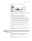
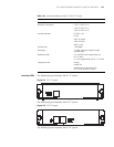
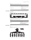
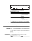
Interface LEDs FIC-8T1 and FIC-8T1-F panels look the same. The following figure illustrates a
FIC-8T1 panel.
Figure 219 FIC-8T1 panel
The following table describes the LEDs on the card panels:
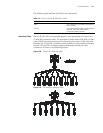
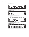
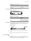
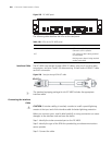
Interface Cable The following figure illustrates the 8T1 conversion cable for the FIC-8T1/FIC-8T1-F
card.
Figure 220 8T1 conversion cable
Operating mode CT1, ISDN PRI (only supported by the
FIC-8T1)
FT1 (only supported by the FIC-8T1-F)
Supported service 1) Backup
2) Terminal access service
3) ISDN PRI (supported by the FIC-8T1)
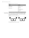
Table 120 LEDs on the FIC-8T1 and FIC-8T1-F panels
Attribute Description
Table 121 LEDs on FIC-8T1 and FIC-8T1-F panels
LED Description
LINK OFF means no link is present; ON means a
link is present.
ACTIVE OFF means no data is being transmitted or
received. ON means data is being
transmitted and/or received.