


FIC-2SAE/FIC-4SAE/FIC-8SAE 155
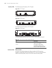
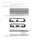
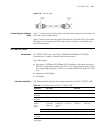
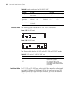
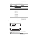
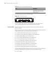
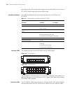
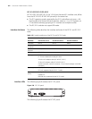
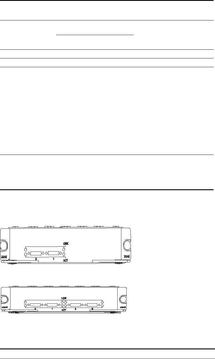
Interface LEDs The following figures show the FIC-2SAE and FIC-4SAE panels:
Figure 178 FIC-2SAE panel
Figure 179 FIC-4SAE panel
The following table describes the LEDs on the FIC-2SAE/ FIC-4SAE panel:
Interface standard and
operating mode
V.24 V.35, RS449, X.21,
RS530
RS232
DTE,
DCE
DTE DCE
Min. baud rate(bps) 1200 1200 300
Max. baud rate(bps) 64 k 4.096 M 2.048 M 115.2
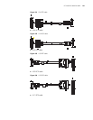
Cable V.24 (RS232) DTE cable
V.24 (RS232) DCE cable
V.35 DTE cable
V.35 DCE cable
X.21 DTE cable
X.21 DCE cable
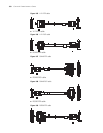
RS449 DTE cable
RS449 DCE cable
RS530 DTE cable
RS530 DCE cable
Supported service 1) DDN leased line
2) Terminal access service
1) Dialup through modem
2) Backup
3) Asynchronous leased line
4) Terminal access service
Table 109 Interface attributes of the FIC-2SAE/FIC-4SAE/FIC-8SAE
Attribute
Description
Synchronous Asynchronous
Table 110 LEDs on the FIC-2SAE/FIC-4SAE panel
LED Description
LINK OFF means no link is present; ON
means a link is present.