


SIC-4FSW/SIC-4FSW-PoE/DSIC-9FSW/DSIC-9FSW-PoE 41
In addition, there is a POE LED on each board, which is provided for the
corresponding boards (SIC-4FSW-POE and DSIC-9FSW-POE) with the POE
function.
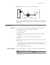
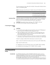
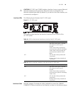
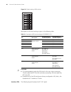
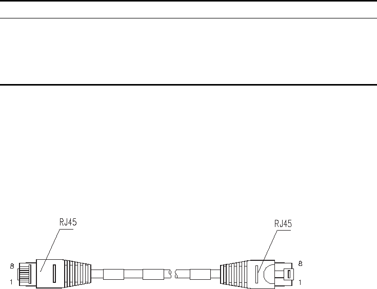
Interface Cable Normally, category-5 twisted pair cable is adopted to connect the 10BASE-T
/100BASE-TX Ethernet interface to the Ethernet, as shown in the following figure:
Figure 36 Ethernet cable
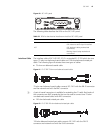
Ethernet cables fall into two categories: straight-through cables and crossover
cables, specifically,
■ Straight-through cable: the wire sequences of the twisted pair cable crimped in
the RJ-45 connectors at both ends are completely the same. It is used to
connect terminal devices (such as PCs, routers) to Hubs or LAN Switches.
■ Crossover cable: The wire sequences of twisted pair cable crimped in the RJ-45
connectors at both ends are different. It can be used to connect two terminal
devices (such as PCs and Routers).
For the pinouts, identification and making methods of these two kinds of network
cables, see Low-End and Mid-Range Series Routers Cable Manual.
Connecting the Interface
Cable
c
CAUTION: You should connect a cable to the port with the correct mark.
Misplugging is prone to impair the interface card and even damage the router.
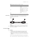
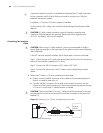
If the SIC has been properly installed, follow these steps to connect the interface
cable:
Step 1: Connect the Ethernet port of SIC to a PC or router using a crossover cable
and to a Hub or LAN Switch using a straight-through cable;
Step 2: Check the status of LINK LED on the panel: ON means the link is connected
and OFF means the link is not connected. In the latter case, check the line.
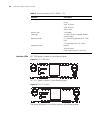
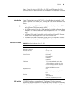
Table 15 LEDs on the panel
LED Description
Steady ON A link is present, but there is no data being
transmitted or received.
OFF No link is present.
Blinking A link is present and there is data being
transmitted and received (ACT).