


FIC-IMA-4E1/FIC-IMA-8E1 213
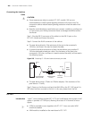
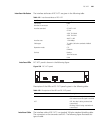
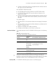
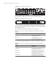
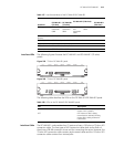
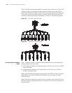
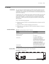
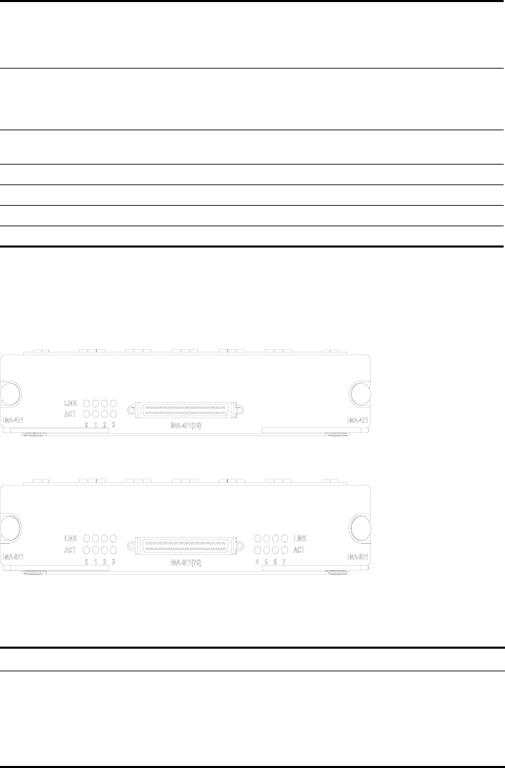
Interface LEDs The following figures illustrate the FIC-IMA-4E1 and FIC-IMA-8E1 (75-ohm)
panels:
Figure 259 75-ohm FIC-IMA-4E1 panel
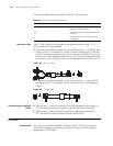
Figure 260 75-ohm FIC-IMA-8E1 panel
The following table describes the LEDs on the FIC-IMA-4E1/FIC-IMA-8E1 panel:
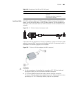
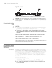
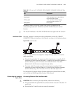
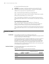
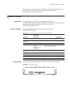
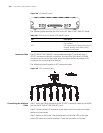
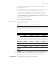
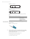
Interface Cable The FIC-IMA-4E1 card provides four E1 ports and uses a 120-ohm or 75-ohm 4E1
conversion cable. The two types of 4E1 conversion cables look similar. Both of
them have a DB-68 connector at one end for connecting the router. However, the
75-ohm 4E1 conversion cable contains eight coaxial cables and the 120-ohm 4E1
conversion cable contains four twisted pairs.
Cable type 75-ohm 4E1
conversion
cable
75-ohm 8E1
conversion
cable
120-ohm
4E1
conversion
cable
120-ohm 8E1 conversion
cable
Max transmission
distance
500 m (1640.4 ft.) 150 m (492.1 ft.)
Operating mode ATM E1 independent link/IMA bundle mode
Supported service AAL5
Protocol PPPoA, PPPoEoA, IPoA, IPoEoA
Transmission rate CBR/VBR-rt/VBR-nrt/UBR
Table 157 Interface attributes of the FIC-IMA-4E1/FIC-IMA-8E1
Attribute
Description
FIC-IMA-4E1
(75-ohm)
FIC-IMA-8E1
(75-ohm)
FIC-IMA-4E1 (120-ohm)
FIC-IMA-8E1
(120-ohm)
Table 158 LEDs on the FIC-IMA-4E1/FIC-IMA-8E1 panel
LED Description
LINK OFF means no link is present; ON
means a link is present.
ACT OFF means no data is being
transmitted or received; blinking
means data is being received or
transmitted.