


152 CHAPTER 4: FLEXIBLE INTERFACE CARDS
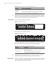
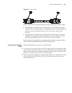
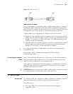
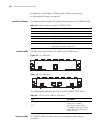
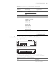
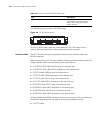
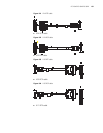
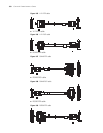
Interface LEDs The following figures illustrate the FIC-1GEF and FIC-2GEF panels:
Figure 175 FIC-1GEF panel
Figure 176 FIC-2GEF panel
The following table describes the LEDs on the FIC-1GEF and FIC-2GEF panels.
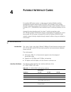
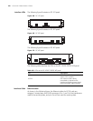
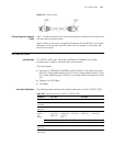
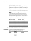
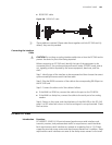
Interface Cable For FIC-1GEF and FIC-2GEF cards, select optical fibers depending on the type of
the installed 1000Base-SX/1000 Base-LX SFP. As the interfaces that these SFP
modules provide use LC-type fiber-optic connectors, you must use fibers with
LC-type connectors for them.
Fiber type 62.5/125
μm
multi-mode
9/125 μm
single mode
9/125 μm
single mode
9/125 μm
single mode
9/125 μm single
mode
Max.
transmission
segment
0.55 km
(0.34 mi.)
10 km (6.21
mi.)
40 km
(24.86 mi.)
40 km (24.86
mi.)
70 km (43.50
mi.)
Operating mode 1000 Mbps
Full duplex
Table 106 Interface attributes of the FIC-1GEF/FIC-2GEF
Attribute FIC-1GEF FIC-2GEF
Table 107 LEDs on the FIC-1GEF/ FIC-2GEF panel
LED Description
LINK OFF means no link is present; ON
means a link is present.
ACT OFF means no data is being
transmitted or received; blinking
means data is being received or/and
transmitted.