


186 CHAPTER 4: FLEXIBLE INTERFACE CARDS
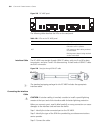
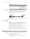
Interface Cable The interface that the FIC-1AE3 provides uses two SMB sockets for data
transmitting and receiving respectively. The ports adopt the 75-ohm unbalanced
transmission mode and are connected to the peer device using a pair of 75-ohm
unbalanced coaxial cables. Several cable length options are available.
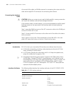
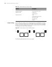
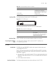
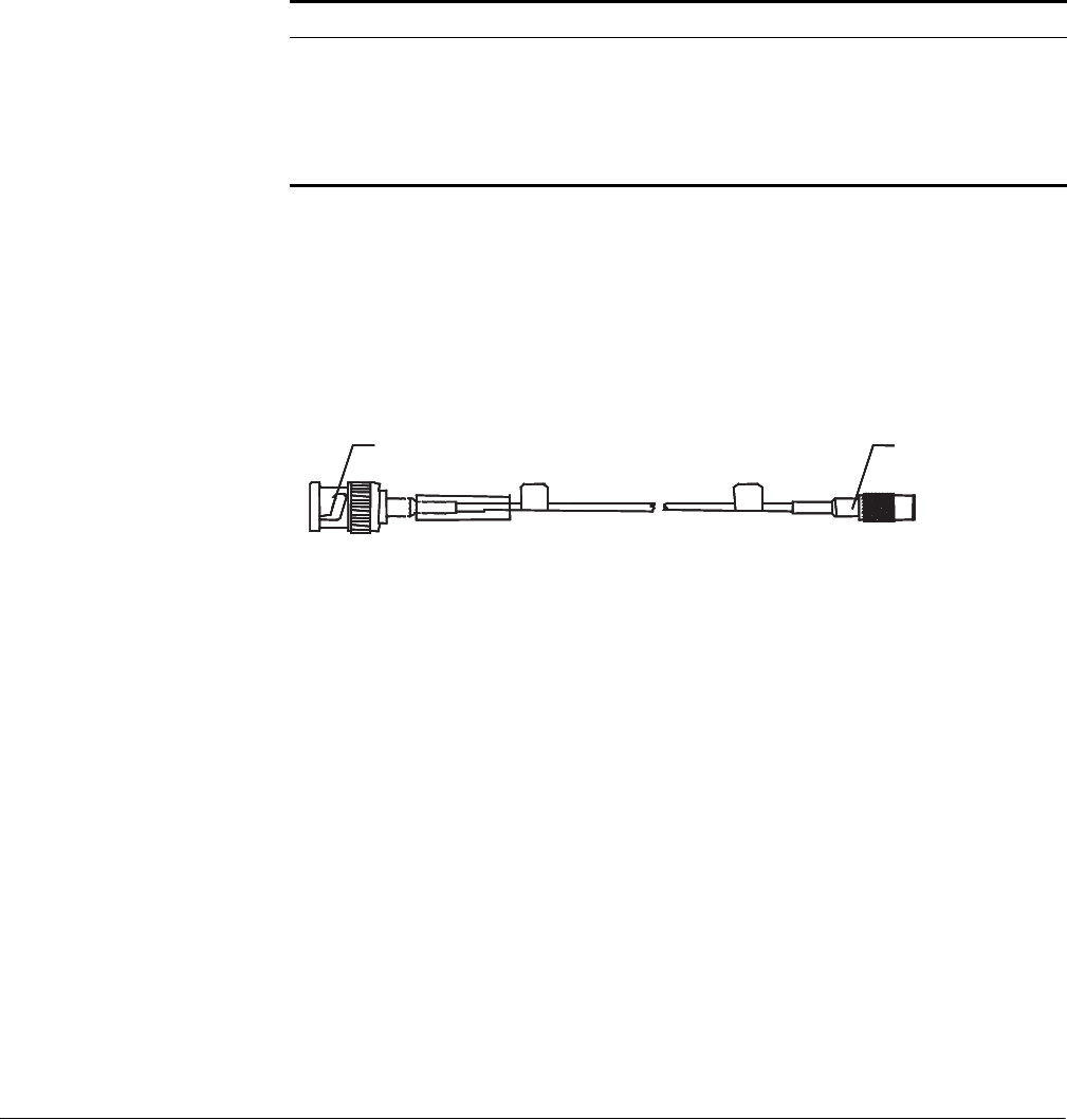
Figure 228 E3/T3 cable
n
The FIC-1AE3 and the FIC-1AT3 use the same type of cables for connection, which
are called E3/T3 cables in this manual.
Connecting the Interface
Cable
c
CAUTION: By design, the FIC-1AE3 is protected against lightning strikes. But
when outdoor cabling is involved, you are recommended to add a special lightning
arrester at the input end of the E3/T3 cable for better protection.
Step 1: Connect the SMB connector of an E3/T3 cable to the Tx port on the
FIC-1AE3 and another end to the Rx port on another device.
Step 2: Connect the SMB connector of another E3/T3 cable to the Rx port on the
FIC-1AE3 and another end to the Tx port on another device.
Step 3: Check the behavior of the LINK LED on the FIC-1AE3 panel: OFF means
fault occurs on the line and the signal is out of synchronization. Check the line
status.
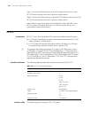
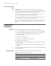
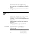
FIC-1AT3
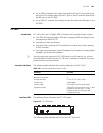
Introduction FIC-1AT3, the 1-port 44 Mbps ATM-T3 interface card, provides these functions:
■ Two ATM cell mapping modes: ADM and PLCP.
■ Scrambling in data transmission.
■ Line clock (when working as DTE interface) and internal clock (when working
as DCE interface).
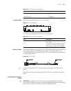
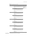
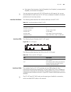
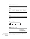
Table 130 LEDs on the FIC-1AE3 panel
LED Description
LINK OFF means no link is present; ON
means a link is present.
ACT OFF means no data is being
transmitted or received; blinking
means data is being received or/and
transmitted.
BNC connector SMB connectorBNC connector SMB connectorBNC connector SMB connectorBNC connector SMB connectorBNC connector SMB connector