


9-8 85330A Multiple Channel Controller
Service
Recommended Test Equipment
Recommended Test Equipment
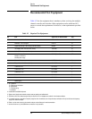
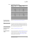
Table 9-2 lists the equipment that is mandatory when servicing the multiple
channel controller and switches. Other equipment can be substituted if it
meets or exceeds the requirements for the tests, or the requirements specified
below.
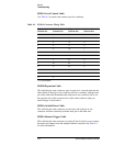
Table 9-2 Required Test Equipment
Qty Item Agilent Part or Model Number Use
1
1 Downloadable Driver Disk 85330-10016
2
I, T, P
1 Multimeter ± 20 Vdc, digital E2377A P, T
1 Digital Oscilloscope (1 MHz Single-shot Band Width) 54501A P, T
1 Tee Adapter (BNC male to female, female) 1250-0781 P, T
3 Cable (BNC male to male 122 cm) 8120-1840 P, T
1 Network Analyzer System
3
50 MHz to 40 GHz
4
,
5
90 dB dynamic range
8722C Option 003 P, T
1 Plotter or Printer
6
HP 7550A+ or LaserJet P
1 Torque Wrench 2.4/3.5 mm (8 in-lb) 8710-1765
7
P, T, I, O
1 TORX Driver T-8 8710-1673 T
1 TORX Driver T-10 8710-1284 T
1 TORX Driver T-15 8710-1816 T
1 Posidriv No.1 8710-0899 T
1 Posidriv No.2 8710-0900 T
1 Soldering Iron T
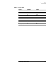
1. O = Operation
P = Performance Verification
A = Adjustments
T = Troubleshooting
I = Installation
2. Included with the 85330A shipment.
3. System must include vector network analyzer, test port cables, and calibration kit.
4. A 50 MHz to 26.5 GHz network analyzer may be used if the 3.5 mm adapters are used with the microwave switches.
5. If a network analyzer is used with a frequency range less than the switches, then the performance verification will only be valid over the frequency
range of the network analyzer.
6. Plotter or printer must connect to the network analyzer and oscilloscope for test documentation.
7. Use this wrench for any 2.4/3.5/SMA mm connections in the procedure.