


85330A Multiple Channel Controller 9-21
Service
Assembly and Disassembly
Switch Control Unit Disassembly
1. Remove the Local Control cable and Switch Drive cable.
2. Remove the four screws from the lid of the Switch Control Unit.
3. Pull the unit apart.
CAUTION Be careful not to damage the gasket seal in each module.
4. Remove the ribbon cable from the Drive module and the Decoder
module.
5. Do not change any switch settings in any of the modules!
Assembly
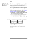
1. If you are installing a new Decoder or Driver module, the switches S1
and S2 must be set correctly. If you are replacing a module, set the
switches for the same setting as the old module. If you are unsure, here
arte the factory default settings:
❍ The Decoder module switches are normally factory set to “all
closed” for S1 and S2.
❍ The Driver module switches are normally factory set to “all closed”
for S1 and S2.
2. Check PAL U2 and U3 in sockets XU2 and XU3 on the Driver module.
The module should contain both PALs, unless there is more than one
driver module. If the SCU has more than one driver module, then only
the first (bottom) should have both XU2 and XU3 filled with a PAL. Any
modules after the first should only have PAL U2 installed. Remove PAL
U3 from socket XU3 for these modules.
3. Make sure that the gasket seal is properly installed in each module
housing.
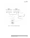
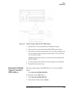
4. Install the A5-A6 ribbon cable as follows:
a. Plug the 16 pin connector into the decoder board socket J3.
b. Plug the 14 pin connector into the decoder board socket J4.
c. Insert the free end of the cable with the 30-pin connector through the
large notch in the driver board from the bottom.
d. Lower the Driver module onto the Decoder module, pulling the
ribbon cable through the opening.
e. Plug the 30 pin connector into the driver board socket J1.
f. Pull the excess length of the ribbon cable up from the Decoder
module into the Driver module. Fold the excess length of the cable
over the top of the driver board.