


85330A Multiple Channel Controller 4-13
General Information
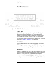
Rear Panel Features
The multiple channel controller may send several receiver trigger pulses
during the measurement sequence, depending on the instructions you sent to
it before starting the run-time mode.
RCVR READY
This positive-edge signal is sent by the receiver when it finished acquiring
data. This line connects to the RECEIVER READY line on the receiver.
AUX 1
Provides a user-controllable TTL line for special applications. The state of
AUX 1 must be set before entering the 85330A’s automatic run-time mode.
The state of AUX 1 is controlled with the ROUTe:CONTrol command.
AUX 2
Provides a user-controllable TTL line for special applications. The state of
AUX 2 can be set in two ways:
• Before entering run-time mode using the ROUTe:CLOSe command.
• During run-time using RUNTime:SWITch:SCAN command.
SRC 1 TRIG
Used in conjunction with SRC 1 READY, controls frequency switching in
the RF source much faster than is possible under 8530A control.This
connects to the TRIGGER IN line of the RF source.
SRC 1 READY
Used in conjunction with SRC 1 TRIG, controls frequency switching in the
RF source much faster than is possible under 8530A control. This connects
to the TRIGGER OUT line of the RF source.
SRC 2 TRIG
Used in conjunction with SRC 2 READY, controls frequency switching in
the LO source much faster than is possible under 8530A control. This
connects to the TRIGGER IN line of the LO source.
SRC 2 READY
Used in conjunction with SRC 2 TRIG, controls frequency switching in the
LO source much faster than is possible under 8530A control. This connects
to the TRIGGER OUT line of the LO source.
REMOTE 1 and 2
These connectors are used to add remote multiple channel controllers in
custom systems—they are not used with the standard instrument.