


85330A Multiple Channel Controller 6-17
Programming
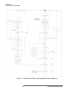
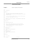
To Use Run-Time Control Mode
Frequency Loop
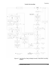
After all switch states have been measured at the first frequency, the
measurements can now be repeated at the next frequency. Here are the steps
that occur during the frequency change:
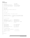
• The first switch state is asserted once more, and the settling time delay
occurs.
• If source 1 triggering is set to TTL (applicable for fast source control
mode), a frequency-incrementing trigger is sent to source 1, and the
85330A waits for the TTL Ready signal before continuing. If a timeout
occurs while waiting for TTL Ready, run-time is aborted and an error
message is issued. The timeout duration can be set using the
RUNT:TIME:SOUR command. When TTL Ready is received, the 85330A
checks the triggering mode of source 2.
If source 1 triggering is set to IMM (applicable for measurements where
the sources are controlled by the 8530A), the 85330A immediately
checks the triggering mode of source 2.
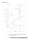
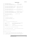
• If source 2 triggering is set to TTL (applicable for fast source control
mode), a frequency-incrementing trigger is sent to source 2, and the
85330A waits for the TTL Ready signal before continuing. If a timeout
occurs while waiting for TTL Ready, run-time is aborted and an error
message is issued. The timeout duration can be set using the 85330A
RUNT:TIME:SOUR command. When TTL Ready is received, the 85330A
re-enters the Switch List Loop so all switch states will be measured at
the new frequency.
If source 2 triggering is set to IMM (applicable to measurements where
the sources are controlled by the 8530A), the 85330A immediately
re-enters the Switch List Loop so all switch states will be measured at
the new frequency.
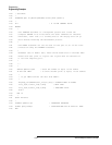
Event Loop
Once all switch states have been measured at all frequencies, the next
“event” can be measured. This would be the next angle in an antenna
measurement system. Stated generically, this is a full repetition of
measurements at all switch states and frequencies for the next “event.” An
“event” being whatever has occurred that caused another Event Trigger
signal. The number of events in the measurement is defined using the
RUNT:EVEN:COUN command.
The sequence now loops back to START EVENT, which is at the beginning
of the event loop. The event loop repeats, measuring all switch states at each
frequency until the number of event loops is completed. When finished, the
85330A exits run-time mode and goes into the idle state.