


9-20 85330A Multiple Channel Controller
Service
Assembly and Disassembly
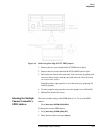
8. Place the E1330 card on top of the 85330-60002 card and slide them
into the mainframe.
9. Tighten all six screws.
E1330 Card
Configuration
Before installing a new E1330 card, make sure that it is configured correctly
for the system that it will be installed in.
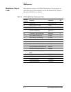
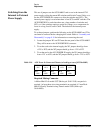
1. The LADDR (logical address) or SW1 should be set to:
This sets the secondary GPIB address to 144. (The secondary address is the
logical address divided by 8, which is 18.)
2. IRQ jumpers JM15 and JM16 are both set to position 1.
3. PULL UP MODE jumpers J51, J52, J53, and J54 are ENABLED.
4. FLG COMBINE jumpers should be empty, NO JUMPERS NEEDED.
85330-60002 Card
Configuration
Before installing a new 85330-60002 card, make sure that it is configured
correctly for the system that it will be installed in.
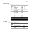
1. Note that sockets J8, J9, and J10 are not normally used.
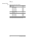
2. Insure that the correct fuses are installed in F1, F2, and F3. Refer to
Table 9-6 on page 9-16 for a list of these fuses.
3. Insure that the correct U2 PAL is installed. Refer to Table 9-6 for the
correct part number.
4. Make sure that the card is set correctly for the system’s trigger (either
positive or negative edged triggering).
NOTE Most positioner controllers put out a positive edged trigger, but most other
trigger sources use a negative edged trigger. The default triggering is
positive edged. To configure the triggering, refer to “Selecting Positive or
Negative-Edge Event Triggers” on page 9-22.
5. Make sure that the correct jumpers are set for internal or external dc
bias. This sets the source of the RF switch dc bias (internal for a small
number of switches, or external for a large number of switches.) The
default is internally powered. To configure the power, see “Switching
from the Internal to External Power Supply” on page 9-24.
Bit 76543210
Set 10010000