


1-10 85330A Multiple Channel Controller
Installation
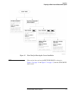
Installing the Switch Control Units and Switches
Installing the Switch Control Units and Switches
Mounting the SCU and
RF Switch
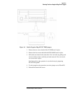
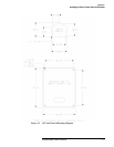
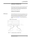
If desired, you can mount the SCU using the supplied mounting screws. You
must provide a mounting plate or drill holes in an existing structure before
mounting an SCU or a switch. Refer to the mounting diagram in Figure 1-5
on page 1-11.
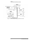
NOTE Make sure the 85383A local control cable can reach from the multiple
channel controller to the SCU. Make sure the 85384A switch drive cable is
long enough to reach from the SCU to the switch.
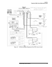
Switch Control Unit
Configuration
Switches
Changing any of the DIP switches inside the SCU is not recommended. All
switch settings are made at the factory.
In a standard system (defined below), the following settings are used:
• SCU address is set to 0.
• Channel numbers 1 through 4 are used to select switch positions.
A “standard system” uses one 85330A with one or two switch control units,
each with a two-throw or four-throw switch module. Remember that 85330A
PORT 1 and PORT 2 are addressed independently. So:
• If you have two SCUs, both can use the default SCU address (0).
• You can use the default channel number assignments (1 through 4) for
both switch modules. Since each SCU is on a different port, and each
port is addressed independently, there is not a channel number conflict.