


Chapter 2 Product Overview
12 Reference Manual LittleBoard 550
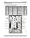
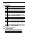
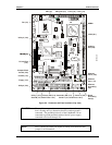
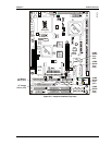
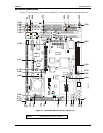
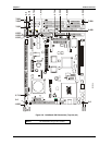
Connector Definitions
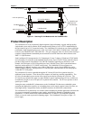
Table 2-2 describes the connectors shown in Figures 2-3 to 2-5. All I/O connectors use 0.1” pin spacing
unless otherwise indicated.
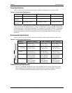
Table 2-2. Connector Descriptions
Jack # Signal Description
J1A/J1B &
J1C, J1D
PC/104 bus 104-pins for PC/104 connector
J2 Fan connector 3-pin header provides +5v and ground to fan.
J3 Video (LCD 1) 50-pin connector part of video output for LCD panels (lower 24-bits)
J4 Video (LCD 2) 16-pin connector part of video output for LCD panels (upper 12 bits)
J5 Video (CRT) 10-pin connector for output to a CRT type monitor
J7 Ethernet 1 8-pin RJ45 connector for Ethernet port 1
J8 Ethernet 1 Optional 6-pin header for Ethernet port 1; for special builds only
J9 Ethernet 2 Optional 6-pin header for Ethernet port 2, for special builds only
J10 Power In 7-pin connector for input power
J11 Serial A 20-pin connector for serial ports 1 and 2
J12 Primary IDE 40-pin connector for the primary IDE interface
J13 Serial B 20-pin connector for serial ports 3 and 4
J14 Floppy 34-pin connector for floppy disk drive interface
J15 Parallel 26-pin connector for parallel interface
J16 Utility 1 16-pin connector for keyboard, external battery, reset switch, speaker
J17 Secondary IDE 40-pin connector for the secondary IDE interface
J18 Utility 3 10-pin connector provides USB2 and USB3 output
J21 PC/104-Plus 120-pin, 2mm, connector for PCI bus
J23 CompactFlash 50-pin socket accepts Type 1 or Type II CompactFlash cards
J24 Utility 2 24-pin connector for mouse, SMBus, USB 0 & 1, power button
J28 Audio In/Out 26-pin, 2mm, connector for all of the Audio signals (input/output)
J31 Video (LVDS) 20-pin, 1.25mm, connector for LVDS type video displays
J32 Ethernet 2 8-pin RJ45 connector for Ethernet port 2
DIMM1 Memory 168-pin socket for SDRAM DIMMs
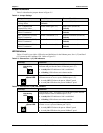
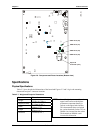
Additional Components
The fuses in Table 2-3 are shown in Figures 2-4 and 2-6.
Table 2-3. Additional Component Descriptions
Component Description
F1 (1.5A) Auto Reset Overcurrent Fuse for USB0 on connector J24
F2 (1.5A) Auto Reset Overcurrent Fuse for USB1 on connector J24
F3 (1.5A) Auto Reset Overcurrent Fuse for USB2 on connector J18
F4 (1.5A) Auto Reset Overcurrent Fuse for USB3 on connector J18
F5 (1.5A) Auto Reset Fuse for the CRT on connector J5