


Chapter 3 Hardware
LittleBoard 550 Reference Manual 59
Miscellaneous
Real Time Clock (RTC)
The LittleBoard 550 contains a Real Time Clock (RTC) and along with the CMOS RAM are backed up
with a Lithium Battery. If the battery is not present or has failed the BIOS has a battery-free boot option
to complete the boot process.
Temperature Monitoring
The MAX1617 performs the temperature monitoring function and has an inputs from the thermal diode
in the VIA Eden CPUs. The SMBus is connected to a dedicated thermal alert pin in the MAX1617 and
the other devices on the SMBus, including the Southbridge (VT82C686B).
NOTE The LittleBoard 550 requires a heatsink for all VIA Eden CPUs and the
Twister-T Northbridge, but no fans.
Oops! Jumper (BIOS Recovery)
The Oops! jumper is provided in the event the BIOS settings you’ve selected prevent you from booting
the system. By using the Oops! jumper you can prevent the current BIOS settings in the EEPROM from
being loaded, forcing the use of the default settings. Connect the DTR pin to the RI pin on serial port 1
(COM 1) prior to boot up to prevent the present BIOS settings from loading. After booting with the
Oops! jumper in place, remove the Oops! jumper and go into BIOS Setup. Change the desired BIOS
settings, or select the default settings, and save changes before rebooting the system.
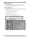
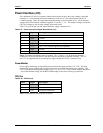
To convert the Serial A interface to an Oops! jumper, short together the DTR (7) and RI (8) pins on
Serial A (J11) header for Serial Port 1. As an alternate, short the equivalent pins, 4 and 9, on the Serial
Port 1 DB9 connector as shown in Figure 3-2.
Serial A Interface (J11)
for Serial Port 1
(or COM1 Port)
1
2
3
4
5
6
7
8
9
10
20
19
Top View
54321
9876
Standard DB9 Serial
Port Connector (Female)
Rear View
Or
LB550Oopsjumper
Figure 3-2. Oops! Jumper Connection
Serial Console
The LittleBoard 550 supports the serial console (or console redirection) feature. This I/O function is
provided by an ANSI-compatible serial terminal, or the equivalent terminal emulation software running
on another system. This can be very useful when setting up the BIOS on a production line for systems
that are not connected to a keyboard and display.
Serial Console Setup
The serial console feature is implemented by connecting a standard null modem cable or a modified
serial cable (or “Hot Cable”) between one of the serial ports, such as Serial 1 (J11A), and the serial
terminal or a PC with communications software. The BIOS Setup Utility controls the serial console
settings on the LittleBoard 550. Refer to Chapter 4, BIOS Setup for the settings of the serial console
option, the serial terminal, or PC with communications software and the connection procedure.
Hot (Serial) Cable
To convert a standard serial cable to a Hot Cable, certain pins must be shorted together at the Serial port
connector or at the DB9 connector. Short together the RTS (4) and RI (8) pins on Serial A (J11) header,