


Chapter 3 Hardware
LittleBoard 550 Reference Manual 47
Utility Interfaces
The Utility interfaces consists of three connectors that provide the standard interface signals, which
include the:
• Utility 1
♦ Keyboard
♦ External battery connection
♦ Reset Switch
♦ PC Speaker
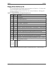
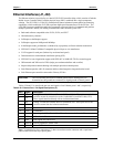
• Utility 2
♦ PS/2 Mouse
♦ SMBus signals
♦ USB signals for USB ports 1 and 2
♦ Power button signal
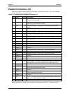
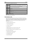
• Utility 3
♦ USB signals for USB ports 3 (USB0) and 4 (and USB1)
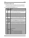
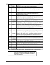
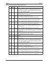
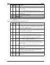
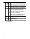
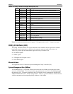
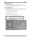
Utility 1 Interface (J16)
Utility 1 interface consists of a 16-pin connector and is used to interface the various utility signals to an
external board with external connections or directly to the respective connector, such as, a keyboard,
speaker, etc. Table 3-17 gives the pin outs and interface signals for the Utility 1 interface.
• Keyboard
• Battery
• Reset Switch
• Speaker
Keyboard Interface
The signal lines for the PS/2 keyboard are provided through the Utility 1 interface (J16), which is also
fully PC/AT compatible.
External Battery
An external battery input connection is provided through the Utility 1 interface (J16) for the Real Time
Clock’s operation in the event the on-board battery is not used.
Reset Switch
The signal lines for a reset switch (hard or soft) are provided through the Utility 1 interface (J16).
NOTE To perform the equivalent of a power-on reset, the reset button
must be pressed and held for a minimum of three seconds.
PC Speaker
The signal lines for a speaker port with 0.1-watt drive are provided through a Utility 1 interface (J16).