


Chapter 3 Hardware
LittleBoard 550 Reference Manual 49
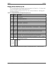
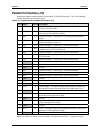
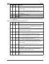
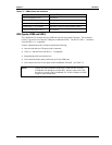
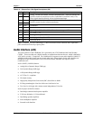
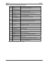
Table 3-17. SMBus Reserved Addresses
Component Address Binary
Serial EEPROM (SEEP) 1010,010x
b
SDRAM EPROM 1010,000x
b
Clock Generator (ICS9250) 1101,001x
b
Southbridge (VT82C686B) 0000,000x
b
(default) Programmable Master
Thermal Sensor (MAX1617) 0011,0010x
b
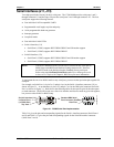
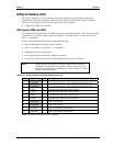
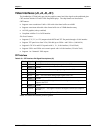
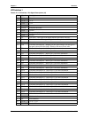
USB Signals (USB0 and USB1)
The LittleBoard 550 contains one root USB hub with four functional USB ports. This connector
(Utility 2) provides two of the four USB ports (USB0 and USB1). The hub is USB v.1.1 and Intel
Universal HCI v.1.1 compatible.
Features implemented in the USB ports include the following:
• One root hub and two USB ports on this connector
• USB v.1.1 and Intel Universal HCI v.1.1 compatible
• Integrated physical layer transceivers
• Over-current detection status (software) on all four USB ports
• Over-current fuses for all four ports on the LittleBoard 550 board. See Table 2-3.
NOTE Ampro does not recommend connecting a USB boot device to the
LittleBoard 550 through an external hub. Instead, connect the USB
boot device directly to the LittleBoard 550. Refer to Chapter 4, BIOS
Setup for more information.