


Chapter 3 Hardware
LittleBoard 550 Reference Manual 43
Serial Interfaces (J11, J13)
Two chips provide the circuitry for the 4 serial ports. The VT86C686B provides serial ports 1 and 2
through connector J11 and the Super I/O provides serial ports 3 and 4 through connector J13. The four
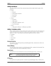
serial ports support the following features:
• Four individual 16550-compatible UARTs
• Programmable word length, stop bits and parity
• 16-bit programmable baud rate generator
• Interrupt generator
• Loop-back mode
• Four individual 16-bit FIFOs
• Serial A Interface (J11)
♦ Serial Port 1 (COM1) supports RS232/RS485/RS422 and full modem support
♦ Serial Port 2 (COM2) supports RS232/RS485/RS422
• Serial B Interface (J13)
♦ Serial Port 3 (COM3) supports RS232/RS485/RS422 and full modem support
♦ Serial Port 4 (COM4) supports RS232/RS485/RS422
NOTE The RS232 and RS485/RS422 modes can be selected for any serial port in
BIOS Setup under BIOS and Hardware Settings menu screen. However,
the RS232 mode is the default selection (Standard) for any serial port.
Refer to the topic On-Board Serial Ports under Power Management and
Advanced User Options in Chapter 4, BIOS Setup for more information.
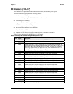
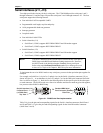
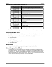
To implement the two-wire RS485 mode on any serial port, you must tie the equivalent pins together for
each port.
For example; on Serial Port 1, tie pin 3 to 5 and pin 4 to 6 at the Serial A interface connector (J11) as
shown in Figure 3-1. As an alternate, tie pin 2 to 3 and pin 7 to 8 at the DB9 serial connector for Serial
Port 1 as shown in Figure 3-1. Refer also to the following tables for the specific pins for the other ports
on each connector. The RS422 mode uses a four-wire interface and does not need any pins tied together,
but you must select RS485 in BIOS Setup.
Serial A Interface (J11)
for Serial Port 1
(or COM1 Port)
1
2
3
4
5
6
7
8
9
10
20
19
Top View
54321
9876
Standard DB9 Serial
Port Connector (Female)
Rear View
Or
L
B
5
5
0R
S
4
8
5
c
o
n
n
Figure 3-1. RS485 Serial Port Implementation
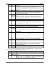
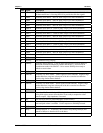
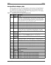
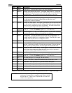
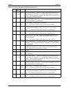
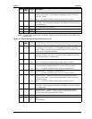
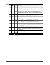
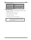
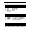
Table 3-14 gives the pins and corresponding signals for the Serial A interface connector (Serial Ports 1
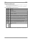
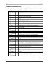
and 2) and Table 3-15 gives the pins and corresponding signals for the Serial B interface connector
(Serial Ports 3 and 4).