


Chapter 3 Hardware
LittleBoard 550 Reference Manual 61
Power Interface (J10)
The LittleBoard 550 uses five separate voltages on the board, but only one of the voltages is provided
externally (+5 volts) through the external connector, which uses a 7-pin vertical header with 0.156”
(3.96mm) spacing. Holes for a right angle mounting header are also available at J10. All the onboard
voltages are derived from the externally supplied +5 volts DC +/- 5%. The onboard voltages provide the
CPU core voltages as well as other voltages used on the board.
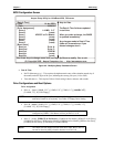
Table 3-27 gives the pin outs and signals for Power supply connector (J10).
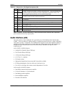
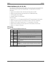
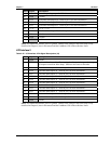
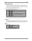
Table 3-27. Power Interface Pin/Signal Descriptions (J10)
Pin # Signal Description
1 +5V +5.0 volts DC +/- 5%
2 GND Ground
3 GND Ground
4 +12V This +12V is are for BUS power only (optional)
5 +3.3V This +3.3V is for BUS power only (optional)
6 GND Ground
7 +5V +5.0 volts DC +/- 5%
Notes: The shaded area denotes power or ground. The +12Vand +3.3V on the Power Interface
connector (J10) are used for the PCI and ISA bus power and must be supplied externally. The -5V
and –12V are supplied from an external power supply through the Utility 1 connector (J16).
Power Monitor
Power supply monitoring is performed by the precision triple supply monitor, LTC 1326. This chip
monitors the system voltages and provides an auto-reset or external push button reset capability. The
LTC 1326 monitors three separate voltages Vcore, +5V, and +3.3V. If any of these voltages drop below
–10% of the nominal voltage, the POWER GOOD output is driven low causing a system reset.
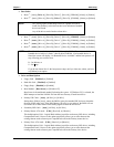
CPU Fan
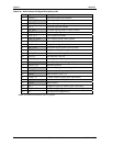
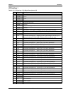
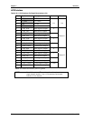
Table 3-28. CPU Fan (J2)
Pin # Signal Description
1 GND Ground
2 +5 +5.0 volts DC +/- 5%
3 TAG Fan Speed Tachometer
Note: The shaded area denotes power or ground.