


Chapter 3 Hardware
56 Reference Manual LittleBoard 550
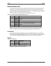
LCD Interface 1
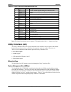
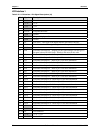
Table 3-24. LCD Interface 1 Pin/Signal Descriptions (J3)
Pin # Signal Description
1 GND Ground
2 +3.3V +3.3V
3 +12V +12V
4 GND Ground
5 FPCLK Flat panel shift clock
6 GND Ground
7 FPDE Flat panel display enable
8 GND Ground
9 LP Line Pulse – This signal is the digital monitor equivalent of HSYNC
10 FLM First Line Marker – This signal is digital monitor equivalent of VSYNC
11 GND Ground
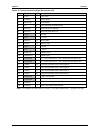
12 FP0 Flat Panel Data Output 0 – Mapping for this signal changes with the type of
flat panel selected in BIOS Setup. ⊗Refer to the notes for this table.
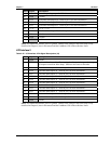
13 FP1 Flat Panel Data Output 1 – Refer to pin 12 for more information.
14 FP2 Flat Panel Data Output 2 – Refer to pin 12 for more information.
15 FP3 Flat Panel Data Output 3 – Refer to pin 12 for more information.
16 FP4 Flat Panel Data Output 4 –Refer to pin 12 for more information.
17 FP5 Flat Panel Data Output 5 – Refer to pin 12 for more information.
18 FP6 Flat Panel Data Output 6 – Refer to pin 12 for more information.
19 FP7 Flat Panel Data Output 7 – Refer to pin 12 for more information.
20 FP8 Flat Panel Data Output 8 – Refer to pin 12 for more information.
21 FP9 Flat Panel Data Output 9 – Refer to pin 12 for more information.
22 FP10 Flat Panel Data Output 10 – Refer to pin 12 for more information.
23 FP11 Flat Panel Data Output 11 – Refer to pin 12 for more information.
24 FP12 Flat Panel Data Output 12 – Refer to pin 12 for more information.
25 FP13 Flat Panel Data Output 13 – Refer to pin 12 for more information.
26 FP14 Flat Panel Data Output 14 – Refer to pin 12 for more information.
27 FP15 Flat Panel Data Output 15 – Refer to pin 12 for more information.
28 FP16 Flat Panel Data Output 16 – Refer to pin 12 for more information.
29 FP17 Flat Panel Data Output 17 – Refer to pin 12 for more information.
30 FP18 Flat Panel Data Output 18 – Refer to pin 12 for more information.
31 FP19 Flat Panel Data Output 19 – Refer to pin 12 for more information.
32, 33 +5V +5V +/- %5
34 +3.3V +3.3V +/- %5
35, 36 NC Not Connected
37 +3.3V +3.3V +/- %5
38 ENAVEE Enable VEE