


Chapter 3 Hardware
50 Reference Manual LittleBoard 550
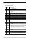
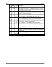
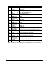
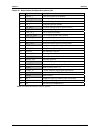
Table 3-18. Utility 2 Interface Pin/Signal Descriptions (J24)
Pin # Signal I/O Description
1 SUSC* - Lid Switch
2 PWRBT* I Power Button
3 BATLOW* I- Low Battery
4 NC O Not Connected (IR Mode Select)
5 Reserved O Reserved (IrDA Transmit)
6 Reserved I Reserved (IrDA Receive)
7 GND - Ground
8 VCC - +5 volts
9 MDATA I/O Mouse Data
10 MCLK I/O Mouse Clock
11 GND - Ground
12 VCC - +5 volts
13 SMBCLK - SMBus Clock
14 SMBDATA - SMBus Data
15 USB1PWR - +5V USB 1 Port Power – Port is disabled if this input is low.
16 USB2PWR - +5V USB 2 Port Power – Port is disabled if this input is low.
17 USBP1- I/O Universal Serial Bus Port 1 Data Negative
18 USBP2- I/O Universal Serial Bus Port 2 Data Negative
19 USBP1+ I/O Universal Serial Bus Port 1 Data Positive
20 USBP2+ I/O Universal Serial Bus Port 2 Data Positive
21 USB1GND - USB 1 Port ground
22 USB2GND -
USB 2 Port ground
23 SHIELD1 -
USB 1 Port shield (Cable Shield)
24 SHIELD2 - USB 2 Port shield (Cable Shield)
Notes: The shaded area denotes power or ground. The signals marked with * = Negative true logic.