


Chapter 3 Hardware
LittleBoard 550 Reference Manual 29
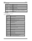
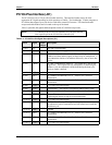
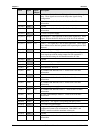
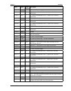
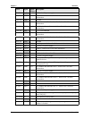
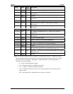
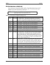
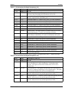
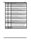
Pin # Signal Input/
Output
Description
103 (D13) +3.3V +3.3 volts ±5% power supply
104 (D14) C/BE2* PCI Bus Command/Byte Enable 2 – Refer to Pin 4 for more
information.
105 (D15) GND Ground
106 (D16) AD19
T/S
PCI Address and Data Bus Line 19 – Refer to Pin 3 for more
information.
107 (D17) +3.3V +3.3 volts ±5% power supply
108 (D18) IDSEL2 Initialization Device Select 2 – Refer to Pin 18 for more
information.
109 (D19) IDSEL3
Initialization Device Select 3 – Refer to Pin 18 for more
information.
110 (D20) GND Ground
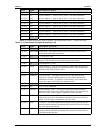
111 (D21) AD27
T/S
PCI Address and Data Bus Line 27 – Refer to Pin 3 for more
information.
112 (D22) AD31
T/S
PCI Address and Data Bus Line 31 – Refer to Pin 3 for more
information.
113 (D23) VI/O +5 volts ±5% power supply
114 (D24) GNT0*
T/S
Grant 0 – Refer to Pin 25 for more information.
115 (D25) GND Ground
116 (D26) CLK1
In
PCI clock 1 – Refer to Pin 27 for more information
117 (D27) GND Ground
118 (D28) RST*
In
PCI bus reset – This signal is an output signal to reset the entire
PCI Bus. This signal will be asserted during system reset
119 (D29) INTC*
O/D
Interrupt C – This signal is used to request interrupts only for multi-
function devices.
120 (D30) GND Ground
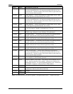
Notes: The shaded area denotes power or ground. The signals marked with * = Negative true logic.
The Input/Output signals in this table refer to the input/output signals listed in the PCI Local Bus
Manual, Revision 2.2, Chapter 2, paragraph 2.1, Signal definitions. The following terms or
acronyms are used in this table:
• In – Input is standard input only signal
• Out – Totem Pole output is a standard active driver
• T/S – Tri-State is a bi-directional input output pin
• S/T/S – Sustained Tri-State is an active low tri-state signal driven by one and only one
agent at a time
• O/D – Open Drain allows multiple devices to share as a wire-OR.