


Chapter 3 Hardware
42 Reference Manual LittleBoard 550
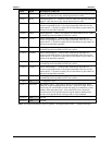
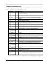
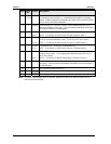
Parallel Port Interface (J15)
Parallel port supports standard parallel, Bi-directional, ECP and EPP protocols. The VIA Southbridge
provides the parallel port interface signals.
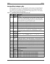
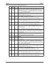
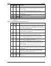
Table 3-13. Parallel Interface Pin/Signal Descriptions (J15)
Pin # Signal In/Out Description
1 Strobe* Out Strobe* – This is an output signal used to strobe data into the printer.
I/O pin in ECP/EPP mode.
2 AUTOFDX* Out
Auto Feed * – This is a request signal into the printer to automatically
feed one line after each line is printed.
3PD0 I/O
Parallel Port Data 0 – This pin (0 to 7) provides parallel port data
signals.
4 ERR* Out Error – This printer output status indicates an error condition on the
printer if the signal state is Low.
5 PD1 I/O Parallel Port Data 1 – Refer to pin 3 for more information.
6
INIT*
Out
Initialize * – This signal is used to Initialize printer. Output in
standard mode, I/O in ECP/EPP mode.
7 PD2 I/O Parallel Port Data 2 – Refer to pin 3 for more information.
8 SLCTIN Out Select In – This output signal is used to select the printer. I/O pin in
ECP/EPP mode.
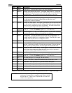
9 PD3 I/O Parallel Port Data 3 – Refer to pin 3 for more information.
10 GND Ground
11 PD4 I/O Parallel Port Data 4 – Refer to pin 3 for more information.
12 GND Ground
13 PD5 I/O Parallel Port Data 5 – Refer to pin 3 for more information.
14 GND Ground
15 PD6 I/O Parallel Port Data 6 – Refer to pin 3 for more information.
16 GND Ground
17 PD7 I/O Parallel Port Data 7 – Refer to pin 3 for more information.
18 GND Ground
19 ACK* In Acknowledge * – This printer output status indicates it has received
the data and is ready to accept new data if the signal state is Low.
20 GND Ground
21 BUSY In Busy – This printer output status indicates the printer is not ready to
accept data if the signal state is High.
22 GND Ground
23 PE In Paper End – This printer output status indicates the printer is out of
paper if the signal state is High.
24 GND Ground
25 SLCT In Select – This printer output status indicates the printer is selected and
powered on if the signal state is High.
26 GND Ground
Notes: The shaded area denotes power or ground. The signals marked with * = Negative true logic.