


Chapter 3 Hardware
LittleBoard 550 Reference Manual 35
IDE Interface (J12, J17)
The LittleBoard 550 provides two IDE connectors for primary and secondary IDE signals.
The EIDE interface logic supports the following features:
• Transfer rate up to 100Mbps
• Increase reliability using Ultra DMA 33/66/100 transfer protocols
• Full scatter-gather capability
• Supports ATAPI and DVD compliant devices
• PIO IDE transfers as fast as 14Mbps.
• Bus master IDE transfers as fast as 100Mbps.
• Single Bus Master EIDE
• Supports two IDE drives per interface channel (primary or secondary connector)
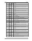
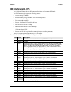
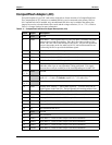
Table 3-9 gives the signals for the IDE 40-pin, 0.100” header.
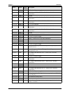
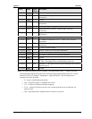
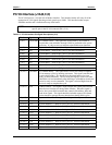
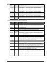
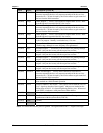
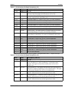
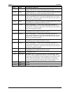
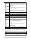
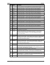
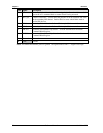
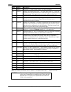
Table 3-9. Primary IDE Interface Pin/Signal Descriptions (J12)
Pin # Signal Description
1 IDERST* IDE Reset – Low active hardware reset (RSTDRV inverted)
2 GND Ground
3 PDD7 Primary Disk Data 7 – These signals (D0-D15) carry the Data, Commands, and
Status between the host and the controller. D0 is the LSB of the even Byte of the
Word. D8 is the LSB of the Odd Byte of the Word. All Task File operations
occur in byte mode on the low order bus D0-D7, while all data transfers are 16
bit using D0-D15 to provide the disk data signals.
4 PDD8 Primary Disk Data 8 – Refer to PDD7 on pin-2 for more information.
5 PDD6 Primary Disk Data 6 – Refer to PDD7on pin-2 for more information.
6 PDD9 Primary Disk Data 9 – Refer to PDD7on pin-2 for more information.
7 PDD5 Primary Disk Data 5 – Refer to PDD7on pin-2 for more information.
8 PDD10 Primary Disk Data 10 – Refer to PDD7 on pin-2 for more information.
9 PDD4 Primary Disk Data 4 – Refer to PDD7 on pin-2 for more information.
10 PDD11 Primary Disk Data 11 – Refer to PDD7 on pin-2 for more information.
11 PDD3 Primary Disk Data 3 – Refer to PDD7 on pin-2 for more information.
12 PDD12 Primary Disk Data 12 – Refer to PDD7 on pin-2 for more information.
13 PDD2 Primary Disk Data 2 – Refer to PDD7 on pin-2 for more information.
14 PDD13 Primary Disk Data 13 – Refer to PDD7 on pin-2 for more information.
15 PDD1 Primary Disk Data 1 – Refer to PDD7 on pin-2 for more information.
16 PDD14 Primary Disk Data 14 – Refer to PDD7 on pin-2 for more information.
17 PDD0 Primary Disk Data 0 – Refer to PDD7 on pin-2 for more information.
18 PDD15 Primary Disk Data 15 – Refer to PDD7 on pin-2 for more information.
19 GND Ground
20 NC/Key Not connected / Key pin plug