


Chapter 2 Product Overview
LittleBoard 550 Reference Manual 13
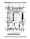
LB550A_01b
L8
L3
L2
L5
CPU (U1)
J2
F5
J5
J4
J3
DIMM1
J31
J21
U27
U26
U4
J28
Y1
Y5
U20
U23 U19
U9
BAT1
E
t
h
e
r
n
e
t
(
U
5
)
Northb
r
i
dg
e
(U2)
Southbridge
(U3)
J1
J18
U34
U10
U15
U17
U11
U16
E
t
h
e
r
n
e
t
(
U
6
)
U21
U25
U14
U12
U8 U7
J12
J17
J14
J13
J15
J16
J24
J11
JP4
JP3
JP7
JP8
JP5
JP6
J10
J7
J32
J23
U24 U22
U33
L9
DIMM1
LCD 1 (J3)
LCD 2 (J4)
LVDS (J31)
Audio In/
Out (J28)
Ethernet
Port 2 (J32)
Power In (J10)Secondary IDE (J17)
CompactFlash
Socket (J23)
Serial B (J13, Serial Ports 3 & 4)
Ethernet
Port 1 (J7)
Floppy (J14)
Primary IDE (J12)
Utility 2 (J24)
Utility 1 (J16)
Parallel (J15)
Utility 3 (J18)
CRT (J5)
PC/104-Plus
(J21)
Serial A (J11, Serial Ports 1 & 2)
J2)Fan (
CRT Fuse (F5)
Board
Grounding
Pad (8)
Ethernet
Grounding
Pad
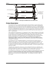
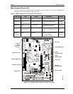
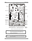
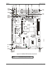
Figure 2-4. Connector and Fuse Locations (Top view)
CAUTION The two Ethernet ports share a common ground (transformer center tap),
that is floating until you determine how the common ground is
connected. The grounding holes (8) of the LittleBoard 550 are
connected to ground potential (return) of the DC power supply
connected to the board through J10.
NOTE Pin-1 is shown as a black pin (square or round) in all connectors and
jumpers in all illustrations.