


Chapter 3 Hardware
LittleBoard 550 Reference Manual 51
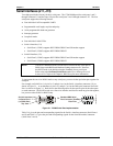
Utility 3 Interface (J18)
The Utility 3 interface is a 10-pin connector used to provide the two of the USB port signals to an
external board with USB connections or directly to the respective USB connector for the USB ports.
Table 3-19 gives the pin outs and interface signals for Utility 3 interface.
• USB ports 2 (USB2) and 3 (USB3)
USB Signals (USB2 and USB3)
The LittleBoard 550 contains one root USB hub with four functional USB ports. This connector (Utility
3) provides two (USB2 and USB3) of the four USB ports. The hub is USB v.1.1 and Intel Universal
HCI v.1.1 compatible.
Features implemented for the USB ports include the following:
• One root hub and two USB ports on this connector
• USB v.1.1 and Intel Universal HCI v.1.1 compatible
• Integrated physical layer transceivers
• Over-current detection status on the USB port (software)
• Over-current fuses for all four ports on the LittleBoard 550 board. See Table 2-3.
NOTE Ampro does not recommend connecting a USB boot device to the
LittleBoard 550 through an external hub. Instead, connect the USB
boot device directly to the LittleBoard 550. Refer to Chapter 4, BIOS
Setup for more information.
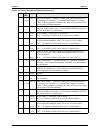
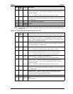
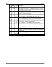
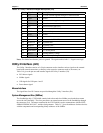
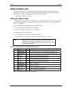
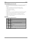
Table 3-19. Utility 3 Interface Pin/Signal Descriptions (J18)
Pin # Signal I/O Description
1 USB3PWR - +5V USB 3 Port Power – Port is disabled if this input is low.
2 USB4PWR - +5V USB 4 Port Power – Port is disabled if this input is low.
3 USBP3- I/O Universal Serial Bus Port 3 Data Negative
4 USBP4- I/O Universal Serial Bus Port 4 Data Negative
5 USBP3+ I/O Universal Serial Bus Port 3 Data Positive
6 USBP4+ I/O Universal Serial Bus Port 4 Data Positive
7 USB3GND - USB 3 Port ground
8 USB4GND -
USB 4 Port ground
9 SHIELD3 -
USB 3 Port shield (Cable Shield)
10 SHIELD4 - USB 4 Port shield (Cable Shield)
Notes: The shaded area denotes power or ground.