


Chapter 3 Hardware
48 Reference Manual LittleBoard 550
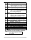
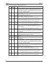
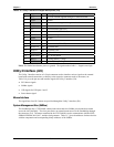
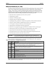
Table 3-16. Utility 1 Interface Pin/Signal Descriptions (J16)
Pin # Signal I/O Description
1 -12 I -12 volts external supplied through I/O Interface board
2 GND I Ground
3 -5V I -5 volts external supplied through I/O Interface board
4 GND I Ground
5 NU O Not used (Power On LED)
6 NC - Not connected (PWR Good)
7 SPKR+ O Speaker + Output
8 GND I Ground
9 RSTSW I Reset Switch
10 NC - Not connected (KBD SW)
11 KBDATA I/O Keyboard Data
12 KBCLK I/O Keyboard Clock
13 GND I Keyboard Ground
14 KBD PWR O +5V for Keyboard
15 BATV+ I +Backup Battery Voltage
16 BATV- I Ground (Battery voltage return)
Notes: The shaded area denotes power or ground. The signals marked with * = Negative true logic.
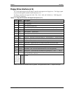
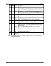
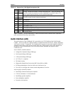
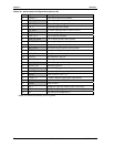
Utility 2 Interface (J24)
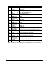
The Utility 2 interface consists of a 24-pin connector used to interface various signals to the external
board with external connections, or directly to the respective connector such as, the mouse, etc.
Table 3-19 gives the pin outs and interface signals for Utility 2 interface (J24).
• PS/2 Mouse signals
• SMBus signals
• USB signals for USB ports 1 and 2
• Power button signal
Mouse Interface
The signal lines for a PS/2 mouse are provided through the Utility 2 interface (J24).
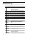
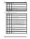
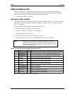
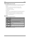
System Management Bus (SMBus)
The Southbridge chip, VT82C686B, contains both a host and slave SMBus port; but the host cannot
access the slave internally. The slave port allows an external master access to the Southbridge through
the connector (J24). The master contained in the VT82C686B is used to communicate with the SEEP,
SDRAM EPROM, MAX1617, and the clock generator. Table 3-17 gives the addresses for these devices
with the components and corresponding binary addresses of the SMBus.