


Chapter 3 Hardware
LittleBoard 550 Reference Manual 55
Video Interfaces (J3, J4, J5, J31)
The Northbridge (VT8606) chip provides the graphics control and video signals to the traditional glass
CRT monitors and the LCD and LVDS flat panel displays. The chip features are listed below:
CRT features:
• Supports a max resolution of 1600 x 1200 with video frame buffer set at 8MB
• Supports a maximum allowable video frame buffer size of 32MB shared memory
• AGP 4X graphics (always enabled)
• Compliant with Rev 2.0 of AGP Interface
Flat Panel features:
• Supports (3.3V, 5V, or 12V) output to both DSTN and TFT flat panels through a 36-bit interface
• Supports TFT panel sizes from VGA (320x480) up to SXGA+ and UXGA+ (1400x1050).
• Supports LCD VGA and SVGA panels with 9-, 12-, 18-bit interface (1 Pixel/Clock)
• Supports UXGA and SXGA active matrix panels with 1x24-bit interface (2 Pixels/Clock)
• Supports 1 or 2 channel LVDS outputs
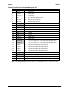
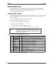
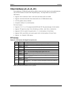
CRT Interface
Table 3-23. CRT Interface Pin/Signal Descriptions (J5)
Pin # Signal Description
1 RED Red – This is the Red analog output signal to the CRT.
2 GND Ground
3 GREEN Green – This is the Green analog output signal to the CRT.
4 GND Ground
5 BLUE Blue – This is the Blue analog output signal to the CRT.
6 GND Ground
7 HSYNC
Horizontal Sync – This signal is used for the digital horizontal sync
output to the CRT.
8 GND Ground
9 VSYNC
Vertical Sync – This signal is used for the digital vertical sync output to
the CRT.
10 +5V +5 volts +/- 5% through Fuse (F5 is next to J5 connector on board)
Notes: The shaded area denotes power or ground.