


Chapter 3 Hardware
LittleBoard 550 Reference Manual 41
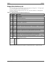
Floppy Drive Interface (J14)
The VT82C686B chip provides the floppy controller and supports two floppy drives. The floppy signals
are provided through the standard 34-pin connector (J14).
The floppy controller will support the 360k, 720k, 1.2M, 1.44M, and 2.88M drives. USB floppy disk
drives are also supported.
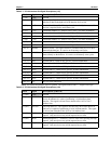
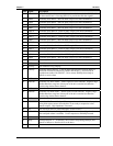
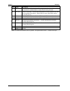
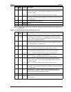
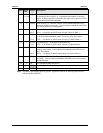
Table 3-12. Floppy Drive Interface Pin/Signal Descriptions (J14)
Pin # Signal Description
2 DRVEN0 Drive (Floppy) Density Select 0
4 NC Not connected
6 NC Not connected (DRATE0)
8 INDEX Index – Sense to detect that the head is positioned over the beginning of a track
10 MTR0 Motor Control 0 – Select drive motor 0.
12 DS1 Drive Select 1 – Select drive 1.
14 DS0 Drive Select 0 – Select drive 0.
16 MTR1 Motor Control 1 – Select drive motor 1.
18 DIR Direction – Direction of head movement (0 = inward motion, 1 = outward motion)
.
20 STEP Step – Low pulse for each track-to-track movement of the head.
22 WDATA Write Data – Encoded data to the drive for write operations.
24 WGATE Write Gate – Signal to the drive to enable current flow in the write head.
26 TRK0 Track 0 – Sense detects the head is positioned over track 0.
28 WRTPRT Write Protect – Senses the diskette is write protected.
30 RDATA Read Data – Raw serial bit stream from the drive for read operations.
32 HDSEL Head Select – Selects the side for Read/Write operations (0 = side 1, 1 = side 0)
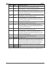
34 DSKCHG
Disk Change – Senses the drive door is open or the diskette has been changed
since the last drive selection.
1, 3, 5, 7,
9, 11, 13,
15, 17, 19,
21, 23, 25,
27, 29, 31,
33
GND Ground
Notes: The shaded area denotes power or ground. The signals marked with * = Negative true logic.