


Chapter 3 Hardware
52 Reference Manual LittleBoard 550
Ethernet Interfaces (J7, J32)
The Ethernet solution is provided by two Intel 82551ER PCI controller chips, which consists of both the
Media Access Controller (MAC) and the physical layer (PHY) combined into a single component
solution. The 82551ER is a 32-bit PCI controller that features enhanced scatter-gather bus mastering
capabilities, which enables the 82551ER to perform high-speed data transfers over the PCI bus. The
82551ER bus master capabilities enable the component to process high-level commands and perform
multiple operations, thereby off-loading communication tasks from the system CPU.
• Backward software compatible to the 82559, 82558, and 82557
• Chained memory structure
• Full duplex or half-duplex support
• Full duplex support at 10Mbps and 100Mbps
• In half-duplex mode, performance is enhanced by a proprietary collision reduction mechanism.
• IEEE 802.3 10BaseT/100BaseT compatible physical layer to wire transformer
• 2 LED support for each port (link/activity are shared and speed)
• Data transmission with minimum interframe spacing (IFS).
• IEEE 802.3u Auto-Negotiation support with IEEE 802.3x 100BASE-TX flow control support
• 3KB transmit and 3KB receive FIFOs (helps prevent data underflow and overflow)
• Improved dynamic transmit chaining with multiple priorities transmit queues
• Each Ethernet port has a RJ-45 connector and the related magnetics integrated on the board.
• Each Ethernet port controller connected to Primary PCI bus
CAUTION The two Ethernet ports share a common ground, that is floating until you
determine how the grounds are connected, to signal ground or chassis ground.
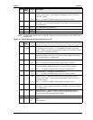
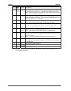
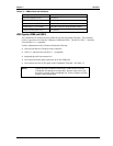
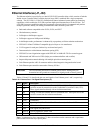
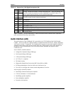
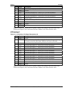
Tables 3-20 and 3-21 describe the pin-outs and signals of two Ethernet ports 1 and 2, respectively.
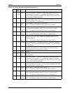
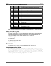
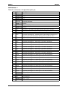
Table 3-20. Ethernet Port 1 Pin/Signal Descriptions (J7)
Pin # Signal Description
1TX+
2TX-
Analog Twisted Pair Ethernet Transmit Differential Pair. These pins transmit the
serial bit stream for transmission on the Unshielded Twisted Pair Cable (UTP).
These signals interface directly with an isolation transformer.
3RX
6RX-
Analog Twisted Pair Ethernet Receive Differential Pair. These pins receive the
serial bit stream from the isolation transformer.
4, 5 Term Termination
7, 8 Term Termination
9 Speed Speed signals (10BaseT or 100BaseT transfer rate) to the Green LED
10 3.3V +3.3 volts +/- 5%
11 Link Link signals for yellow LED
12 Activity Activity signals for yellow LED
13, 14 Shld Grounded Shield
Note: Termination involves connecting a 75 ohm resistor between the connector and a capacitance
plane created on an inner layer power plane.