


Chapter 3 Hardware
LittleBoard 550 Reference Manual 57
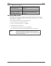
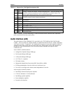
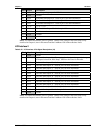
Pin # Signal Description
39 ENAVDD Power sequencing output for LCD driver
40 GND Ground
41 FP20 Flat Panel Data Output 20 – Refer to pin 12 for more information.
42 FP21 Flat Panel Data Output 21 – Refer to pin 12 for more information.
43 FP22 Flat Panel Data Output 22 – Refer to pin 12 for more information.
44 +3.3V +3.3V +/- %5
45 FP23 Flat Panel Data Output 23 – Refer to pin 12 for more information.
46, 47 NC Not Connected
48, 49 GND Ground
50 +12V +12V
Notes: The shaded area denotes power or ground. ⊗Refer to the settings in the BIOS Setup Utility
described in Chapter 4, later in this manual and the LittleBoard 550 Software Release Notes.
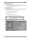
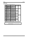
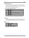
LCD Interface 2
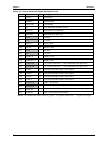
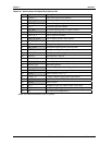
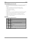
Table 3-25. LCD Interface 2 Pin/Signal Descriptions (J4)
Pin # Signal Description
1, 2 GND Ground
3 FP24
Flat Panel Data Output 24 – The mapping for this signal changes with the type
of flat panel selected in BIOS Setup. ⊗Refer to the notes for this table.
4 FP25 Flat Panel Data Output 25 – Refer to pin 3 for more information.
5 FP26 Flat Panel Data Output 26 – Refer to pin 3 for more information.
6 FP27 Flat Panel Data Output 27 – Refer to pin 3 for more information.
7 FP28 Flat Panel Data Output 28 – Refer to pin 3 for more information. .
8 FP29 Flat Panel Data Output 29 – Refer to pin 3 for more information.
9 FP30 Flat Panel Data Output 30 – Refer to pin 3 for more information. .
10 FP31 Flat Panel Data Output 31 – Refer to pin 3 for more information. .
11 FP32 Flat Panel Data Output 32 – Refer to pin 3 for more information.
12 FP33 Flat Panel Data Output 33 – Refer to pin 3 for more information. .
13 FP34 Flat Panel Data Output 34 – Refer to pin 3 for more information.
14 FP35 Flat Panel Data Output 35 – Refer to pin 3 for more information.
15, 16 GND Ground
Notes: The shaded area denotes power or ground. ⊗Refer to the settings in the BIOS Setup Utility
described in Chapter 4, later in this manual and the LittleBoard 550 Software Release Notes.