


Touch Panel Accessories
20
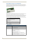
1200V Modero Video Touch Panels
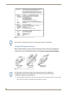
3. Carefully remove the gold-tipped terminal ends of the antenna from their factory default connectors
on the main board. The antenna is secured at this location to restrict its movement prior to
connection to a wireless card.
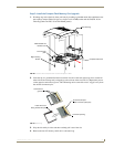
4. Firmly grasp the NXA-PCI80211G mini-PCI card (from the edges) and insert the pins (at a 25°
angle) into the opening on the connector (FIG. 19).
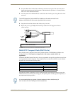
5. While maintaining the 25° angle alignment on the new module, push it in firmly until the contact
pins are completely inside the connector and the card "snaps" into place (FIG. 19).
6. Push the card downward (to the main board) until the side braces snap atop the NXA-PCI80211G
and hold it in place.
7. Locate the terminal ends of the antennas and apply downward pressure to "snap" them onto their
gold-tipped counterparts on the mini-PCI card (FIG. 19). Carefully push down on each connector to
verify it is securely joined to the card.
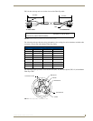
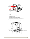
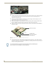
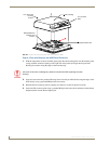
FIG. 18 Location of the mini-PCI card connector on main board
FIG. 19 Installation of the mini-PCI card connector on main board
Connection point
between the braces and
the mini-PCI card
Antennas connectors
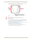
It is recommended that any upgrade of internal equipment be done simultaneously in
order to reduce the risk of damage to internal components.