


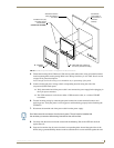
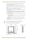


Installation Procedures: NXD-1200V Panels
47
1200V Modero Video Touch Panels
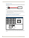
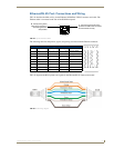
Ethernet/RJ-45 Port: Connections and Wiring
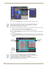
FIG. 44 describes the blink activity for the Ethernet 10/100 Base-T RJ-45 connector and cable. The
Ethernet cable is connected to the side of the Wall Mount panels
The following table lists the pinouts, signals, and pairing associated with the Ethernet connector.
FIG. 45 diagrams the RJ-45 pinouts and signals for the Ethernet RJ-45 connector and cable.
FIG. 44 Layout of Ethernet LEDs
Ethernet RJ-45 Pinouts and Signals
Pin Signals Connections Pairing Color
1 TX + 1 --------- 1 1 --------- 2 Orange-White
2 TX - 2 --------- 2 Orange
3 RX + 3 --------- 3 3 --------- 6 Green-White
4 no connection 4 --------- 4 Blue
5 no connection 5 --------- 5 Blue-White
6 RX - 6 --------- 6 Green
7 no connection 7 --------- 7 Brown-White
8 no connection 8 --------- 8 Brown
FIG. 45
RJ-45 wiring diagram
ETHERNET
10/100
A L
A - Activity LED (yellow)
lights when receiving or
transmitting Ethernet
data packets
L - Link LED (green) lights when
the Ethernet cables are connected
and terminated correctly.
123 456 78
123 456 78