


Installation Procedures: NXD-1200V Panels
41
1200V Modero Video Touch Panels
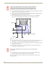
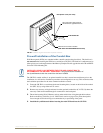
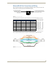
4. Thread the incoming RJ-45, Ethernet, USB, and any other audio/video wiring (from their terminal
locations) through the cutout opening. Refer to the Wiring Guidelines for the 1200V Panels section
on page 45 for pinout descriptions.
Leave enough slack in the wiring to accommodate any re-positioning of the panel.
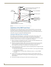
5. Connect all data and power wiring connectors to their corresponding locations along the side of the
(un-powered) NXD touch panel.
Verify the terminal end of the power cable is not connected to a power supply before plugging
in the 2-pin power connector.
The USB connectors can be from a either a USB extension cable, or a wireless USB RF
transmitter.
6. Test the incoming wiring by attaching the panel connections to their terminal locations and applying
power. Verify the panel is receiving power and functioning properly to prevent repetition of the
installation.
7. Disconnect the terminal end of the power cable from the connected power supply.
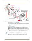
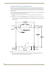
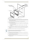
8. Insert the four sets of drywall screws and expansion clips into the four oval notch locations along
the top/bottom edges of the main unit (FIG. 39).
9. Carefully insert the main unit (with expansion clips) into the cutout until the Mounting Tabs on the
NXD unit lie flush against the wall (FIG. 39).
10. Tighten the drywall clip sets (screws and clips) until the Mounting Tabs are securely fastened and
flush against the wall.
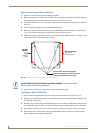
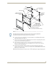
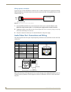
FIG. 39 Wall Mount panel (NXD) installation configuration for drywall surfaces
B - Main NXD unit consists of
Install the four drywall
clip sets (included)
into these holes
the touch panel and housing
4 notches are
required if the
unit is installed in
drywall using the
four (4) provided
drywall expansion
A - Faceplate
(bezel)
clips
Mounting Tab
Don’t disconnect the connectors from the touch panel. The unit must be installed with
the attached connectors before being inserted into the drywall.