


Installation Procedures: NXD-1200V Panels
37
1200V Modero Video Touch Panels
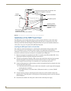
Pre-wall Installation of the Conduit Box
Wall Mount panels (NXDs) are contained within a metallic outer housing (back box). This back box is
not removed when installing the NXD into a conduit box (CB-TP12). The back box is only removed to
either gain access for the replacement of the Memory/Compact Flash or upgrade the unit with an MB-TP
Universal VESA Mounting Kit.
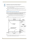
The CB-TP12 conduit wallbox is an optional metallic box that is secured onto stud beams prior to the
installation of a solid surface. Installation procedures and configurations can vary. This section describes
the installation procedures for the most common installation scenario.
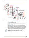
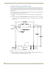
1. Fasten the CB-TP12 to a stud through the stud fastening holes, located on the inside of the conduit
box (FIG. 36), by using either nails or screws.
2. Remove any necessary wiring knockouts from the (optional) conduit box (C in FIG. 36) where the
necessary cables are threaded through for connection to the touch panel.
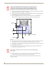
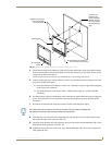
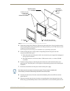
3. Thread the incoming RJ-45, Ethernet, and any other audio/video wiring through the knockouts.
Refer to the Wiring Guidelines for the 1200V Panels section on page 45 for pinout descriptions.
Leave enough slack in the wiring to accommodate any re-positioning of the panel.
4. Install the drywall/sheetrock before inserting the main NXD unit into the CB-TP12.
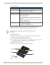
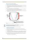
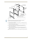
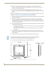
FIG. 35 Installation of grommet into the rear plastic enclosure
Rear plastic cover (rear view)
Rim of the strain relief grommet
should lie flush against enclosure
CLIP FACING UP
VESA mount connection location
(USE ONLY AMX PROVIDED #8-32 screws)
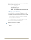
INSTALLER: LEAVE A GAP BETWEEN THE STUD AND CONDUIT BOX TO
ACCOMMODATE THE DRYWALL SHEETROCK. This gap allows the installation of
the drywall/sheetrock after the conduit box has been installed.